In part 1 we compared the directional speaker to a flashlight for sound. It fires sound in one direction only, and outside the aimed direction it stays quiet — but how is that possible? However good a speaker you use, as long as it emits audible sound directly, that sound spreads everywhere. The directional speaker's answer lies in inverting the idea: rather than firing audible sound, you load it onto sound you cannot hear.
Carried on sound you cannot hear — the ultrasonic carrier
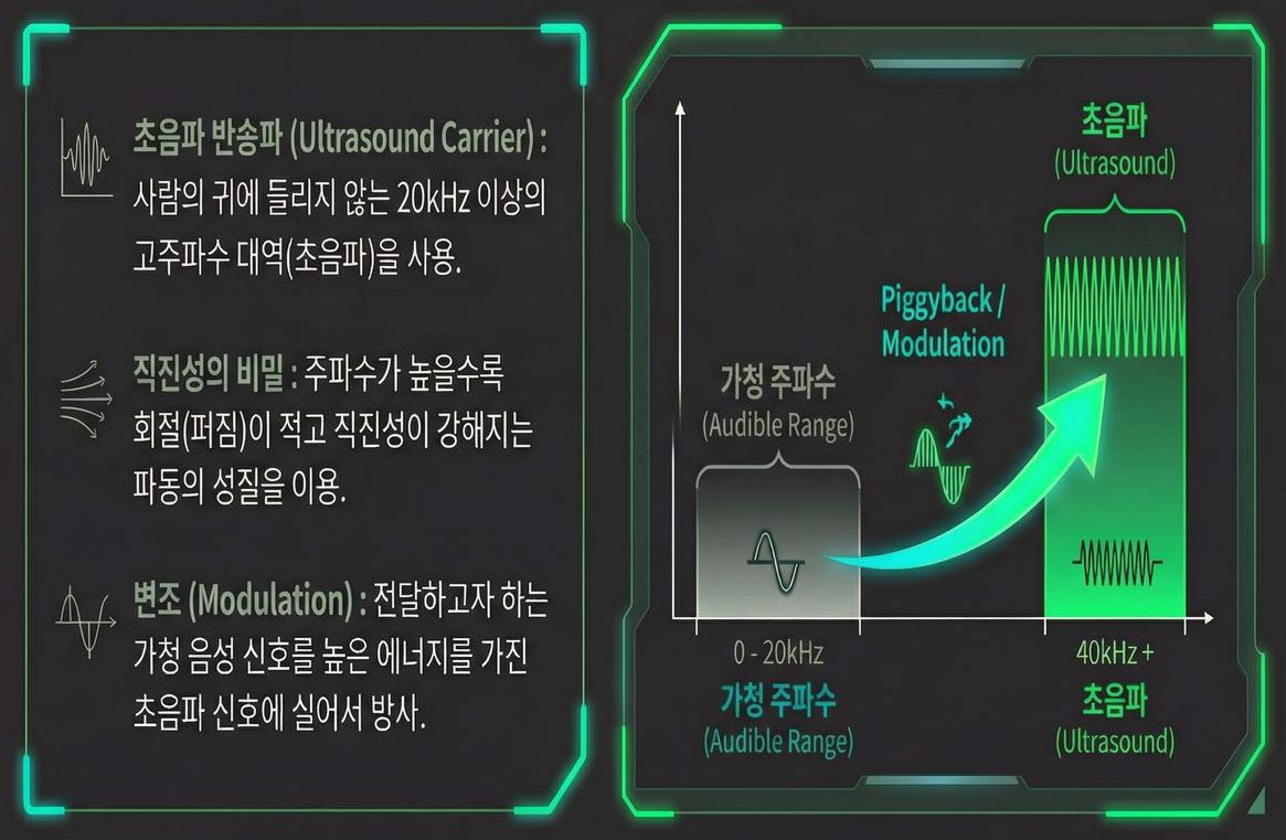
A directional speaker uses the band above 20 kHz, inaudible to human ears — ultrasound — as its carrier. Practical products generally work at 40 kHz or above. Two keys sit here.
- The secret of straight-line travel — the higher the frequency (the shorter the wavelength), the less a wave diffracts, and the more it travels in a straight line. Ultrasound, with a wavelength far shorter than audible sound, travels almost as directly as light. This is the physical basis for the "flashlight-like sound" of part 1.
- Modulation — the audible signal you want to deliver is loaded onto a high-energy ultrasonic signal and radiated. Just as radio carries voice on radio waves, a directional speaker carries voice on ultrasound.
At this point an obvious question arises. Ultrasound is inaudible, so how do we end up hearing the voice loaded onto it — with no receiver and no headphones?
What modulation is — carving sound into the envelope
Modulation in one sentence is "shaking the amplitude of the carrier in step with the sound signal." In amplitude modulation (AM), the most basic form, the emitted waveform takes this shape.
emitted ultrasound = (reference amplitude) × [ 1 + m × sound signal(t) ] × cos(2π × carrier frequency × t)
The bracketed part is the envelope. The ultrasound itself oscillates rapidly at 40 kHz, but the outline of its amplitude traces exactly the shape of the sound we want to deliver. The sound rides not in the waveform but in the outline.
m is the modulation index, which sets how deeply the envelope is shaken. A small m gives quiet sound; as m approaches 1 the sound gets louder but so does distortion. Where you place this single number is the knob that trades loudness against fidelity, and part 14 addresses it directly.
Modulation also creates sidebands on either side of the carrier in the frequency domain. Loading audio up to 20 kHz onto a 40 kHz carrier means the occupied band is actually 20–60 kHz. A design constraint pops out immediately — the bottom edge of the lower sideband touches 20 kHz, the upper limit of hearing. In practice the audio band is therefore truncated from above (8 kHz is ample for voice announcements) or the carrier is placed higher.
The air becomes the speaker — the parametric array
The answer to that question is the heart of the technology: the parametric array. The definition runs like this — when powerful ultrasound passes through air, the nonlinearity of the air attenuates the ultrasound while the audible sound loaded onto it is restored.
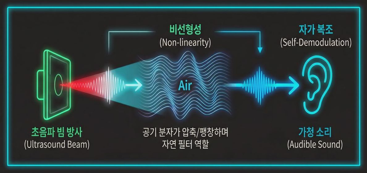
Let us follow the sequence.
- Beam radiation — a powerful ultrasonic beam carrying the voice moves out into the air. Nothing is audible yet.
- Nonlinearity of the air — when the sound pressure is high enough, air is no longer a well-behaved medium. The compressed side propagates slightly faster than the rarefied side, so the waveform distorts itself.
- Self-demodulation — within that distortion, the audible signal loaded onto the ultrasound separates out and comes back to life. The high-frequency ultrasound is absorbed quickly by the air and fades, while the restored audible sound carries much further.
In the end it is not the speaker's diaphragm that makes the sound but the air the beam passes through. The whole path of the ultrasonic beam becomes a long, thin virtual loudspeaker. That is why "the air becomes the speaker" is not an exaggeration, and why someone standing outside the beam hears nothing.
Why it comes back — the second derivative of the squared envelope
The self-demodulation relation formalised in 1965 summarises the phenomenon with remarkable economy. The restored audible pressure is set roughly like this.
audible pressure ∝ the second time derivative of (the envelope squared)
Short as it is, this single line contains every strength and every weakness of the directional speaker.
- The "squared" creates distortion — because the envelope is used squared rather than as-is, harmonics and sum/difference components appear that were never in the original. This is distortion arising from the principle, independent of component quality. In practice engineers therefore apply pre-compensation, sending an envelope with a square root already applied. The square and the square root cancel and the original waveform returns.
- The "second derivative" cuts the bass — one time derivative is equivalent to a gain rising in proportion to frequency, so two derivatives produce a 12 dB per octave slope. High notes come out easily and low notes fall away sharply. This term is the exact source of the "weak bass" limitation mentioned in part 1.
Put together, signal processing for a directional speaker is the job of undoing the square (distortion correction) and undoing the second derivative (bass compensation) at the same time. How far these two corrections can be pushed is precisely what determines a product's sound quality; parts 12–14 cover the concrete techniques.
Why air, of all media — water is more nonlinear
Something odd sits here. This technology was born underwater, and nonlinearity itself is greater in water than in air. The coefficient β describing a medium's degree of nonlinearity is about 3.5 for water but only 1.2 for air. Air is close to an ideal gas, so β = 1 + (γ−1)/2, and inserting the heat capacity ratio γ = 1.4 for a diatomic gas gives 1.2 directly.
And yet the method works far better in air. The reason is that difference-frequency generation is governed not by β alone but by β divided by the medium's ρc³, where ρ is density and c is the speed of sound.
| Medium | Density ρ | Speed of sound c | Nonlinearity β | ρc³ |
|---|---|---|---|---|
| Air (20 °C) | 1.2 kg/m³ | 343 m/s | 1.2 | about 48 million |
| Water | 1,000 kg/m³ | 1,500 m/s | 3.5 | about 3.4 trillion |
On ρc³ alone, water is about 70,000 times that of air. Even allowing water its nearly threefold advantage in β, the difference-frequency component obtainable from the same sound pressure favours air by more than twenty thousand times. Air being a "soft" medium turns into an overwhelming advantage here.
The price is equally clear. Air absorbs ultrasound quickly, so the beam loses its strength within a few metres. That is why the parametric array serves underwater as sonar reaching kilometres, while in air it becomes an indoor device working over metres to tens of metres. The same principle becomes an entirely different product depending on the medium.
How the carrier frequency is chosen
The higher the carrier, the narrower the beam — but the faster the air consumes it. The values below assume a 100 mm circular array, using the international standard formulation (20 °C, 50 % RH) and the directivity of a circular aperture.
| Carrier frequency | Wavelength | Beamwidth (−3 dB, 100 mm aperture) | Air absorption | Practical assessment |
|---|---|---|---|---|
| 25 kHz | 13.7 mm | about 8.1° | 0.73 dB/m | Long range, but risk of audible leakage |
| 40 kHz | 8.6 mm | about 5.0° | 1.32 dB/m | The most widely used balance point |
| 60 kHz | 5.7 mm | about 3.4° | 1.98 dB/m | Sharper beam, but range is lost |
| 100 kHz | 3.4 mm | about 2.0° | 3.28 dB/m | Short range only; transducers hard to source |
The table shows why 40 kHz has become a de facto standard. It sits far enough above the hearing limit that the carrier is unlikely to be heard directly, its absorption is manageable, and inexpensive piezoelectric transducers cluster in this band. Transducer resonance behaviour is covered in parts 9 and 10.
Hardware evolution — from dome to array
The hardware realising the principle has also evolved through generations.
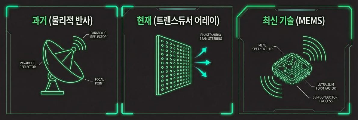
- Past — physical reflection: a dome shaped like a dish antenna (a parabolic reflector) gathers the sound. Simple in principle, but bulky and awkward to install.
- Present — transducer array: many small ultrasonic transducers are arranged on a plane, and the phase of each element is controlled to steer the beam and shape the sound pressure. A single thin panel forms the beam with no reflector, and the aiming direction can be changed electronically.
- Latest — MEMS speakers: ultra-miniature speaker chips built with semiconductor processes. Miniaturisation and thinning are reaching the point of fitting into mobile devices.
Planar arrays with phase control are how the planar source of part 1 is actually built, and the subject is covered in detail under the name beamforming in part 8. The beamwidths in the table above are ultimately a question of how large you make the aperture, so the size of the array is the size of the directivity.
The path a signal takes inside one speaker
That is the physics. Inside a real unit, the signal passes through several stages in order so that the physics can be put to work. Each stage does a different job, and each shows a different symptom when it is done poorly. It is worth standing the concepts scattered through the previous sections in a single line to see where each one sits.
| Stage | What it does | If this stage is weak |
|---|---|---|
| 1. Input and band limiting | Takes in the audio and cuts the upper limit. For voice announcements the cut is usually near 8 kHz | The lower sideband descends below 20 kHz and components near the carrier become directly audible |
| 2. Bass compensation | Lifts in advance exactly what the second derivative removes at 12 dB per octave | Voices turn thin and reedy, and intelligibility drops at the same volume |
| 3. Pre-compensation — envelope shaping | Undoes in advance the squaring that the air will apply (square-root style shaping) | Harmonics and sum-and-difference components survive intact, giving a coarse, muddied sound |
| 4. Modulation | Places the shaped envelope on the carrier. The modulation index m trades volume against distortion | Raising m makes it louder but distortion climbs with it; lowering m makes it quiet |
| 5. Amplification and drive | Supplies enough voltage and current to shake hundreds of elements at once | Peaks clip, the envelope is flattened, and every correction upstream is rendered pointless |
| 6. Transducer array | Converts electricity into ultrasound and forms the beam from the phase differences between elements | Frequencies away from resonance radiate poorly, narrowing the band that can be carried |
| 7. The air | Acts as the demodulator. Sound is created all along the path the beam travels | When temperature and humidity change, absorption changes, and volume and range shift together |
The order is the striking part. The corrections sit at the front, and the cause of the distortion sits at the very back. In an ordinary speaker the component that generates the distortion is at the end of the chain with nothing after it to work on; a parametric speaker knows in advance that the agent of distortion is the air, and knows its equation too. That makes it possible to run the calculation backwards and place the answer upstream. Saying distortion is intrinsic to the principle does not only mean it is unavoidable — it also means it is computable.
At the same time, the chain is governed by its weakest link. However refined the pre-compensation, it counts for nothing if the waveform is clipped at stage 5; and if the band at stage 6 is narrow, the bass so carefully lifted at stage 2 is never radiated in the first place. That is why signal processing and hardware cannot be optimised separately, and why this series carries physics, circuits and signal processing side by side.
One addition regarding stage 4. The same phenomenon is often explained with two ultrasonic tones: emit 40 kHz and 41 kHz together and the 1 kHz difference becomes audible. This is not a different principle but the same equation cut a different way. Describing it as shaking the envelope and describing it as decomposing that shaking on the frequency axis into a carrier and sidebands point at the same fact. The two-tone case is simply the simplest instance of it — the case where the sound being carried is a single pure tone.
Where does the sound begin to be audible?
An ordinary speaker is loudest right in front of the diaphragm. A parametric speaker is different. Directly in front of the radiating face there is only ultrasound and almost no audible sound, because the sound is built up gradually as the beam travels through the air.
The curve of level against distance is therefore peculiar. Starting from the radiating face it rises for a while, and only once the carrier has lost its strength to absorption — and can no longer create new sound — does it begin to fall. An ordinary speaker decays from the very start; here the loudest point sits several metres from the speaker.
This has two practical implications. One is that too close is actually worse: using it at 50 cm, as at a kiosk, requires a different design. The other is that the safety margin runs backwards. Where the audible sound is weakest, the ultrasound is strongest, so the closer a person stands to the unit, the less they gain and the more they are exposed. The reason part 3 stresses mounting height and angle so heavily is contained in this one curve.
Three common misconceptions
- "The ultrasound disappears completely" — not accurate. It decreases gradually through absorption, and it is strongest right in front of the speaker. Setting mounting height and angle so that people's heads are not at close range is basic to the design.
- "You only hear it inside the beam" — true only in free space. When the beam hits a wall, floor or glass pane, that spot behaves like a new source and fills the room. What you aim at is half the design.
- "Just modulate and you get sound" — you get sound, but heavily distorted. Raw AM without correcting the squaring and second-derivative terms above struggles to deliver even speech intelligibility.
Three-sentence summary
- Audible speech is loaded onto the envelope of inaudible ultrasound (modulation) and fired as a strongly collimated beam.
- The nonlinearity of the air self-demodulates it, but because the restored sound is the second derivative of the squared envelope, distortion and weak bass follow as a matter of principle.
- The principle is realised with a transducer array and phase control, and the hardware is shrinking from domes to MEMS.
About this series
"The Science of Directional Speakers" continues in the order below.
- What is a directional speaker — a flashlight for sound
- Carrying sound on sound you cannot hear — first steps in the operating principle (this article)
- Directional speaker use cases — exhibitions, safety, retail, offices
- What is ultrasound — definitions, types, propagation
- Then: the parametric acoustic array (PAA), beamforming, piezoelectric transducers, Nyquist, modulation, signal processing
This series reworks, in blog form, self-authored lecture material from the author's own study of ultrasonic directional audio. The figures are drawn from that material.
References
- H. O. Berktay, "Possible exploitation of non-linear acoustics in underwater transmitting applications," JSV 2(4), 435 (1965) : the original source of the "second derivative of the squared envelope" relation used above
- P. J. Westervelt, "Parametric Acoustic Array," JASA 35(4), 535 (1963) : the theory that nonlinear interaction generates difference-frequency components
- M. Yoneyama et al., "The audio spotlight: An application of nonlinear interaction of sound waves to a new type of loudspeaker design," JASA 73(5), 1532 (1983) : realising a parametric loudspeaker in air with a transducer array
- T. Kamakura et al., "Parametric loudspeaker — characteristics of acoustic field and suitable modulation of carrier ultrasound," Electron. Commun. Jpn. 74(9), 76 (1991) : comparison of sound field and distortion by carrier modulation scheme
- "Dynamic single sideband modulation for realizing parametric loudspeaker," AIP Conf. Proc. 1022, 613 (2008) : a modulation technique addressing bandwidth and distortion together through sideband handling
- H. E. Bass et al., "Atmospheric absorption of sound: Further developments," JASA 97(1), 680 (1995) : basis for the absorption coefficients in the table (25 kHz 0.73 · 40 kHz 1.32 · 60 kHz 1.98 · 100 kHz 3.28 dB/m)
- US 5,889,870 — Acoustic heterodyne device and method : obtaining audible sound from an ultrasonic carrier
- Amplitude modulation — Wikipedia : definitions of envelope, modulation index and sidebands
- Sideband — Wikipedia : sidebands around a carrier and occupied bandwidth
- Nonlinear acoustics — Wikipedia : overview of waveform distortion at high sound pressure
- Sound from ultrasound — Wikipedia : the field of generating audible sound from ultrasound