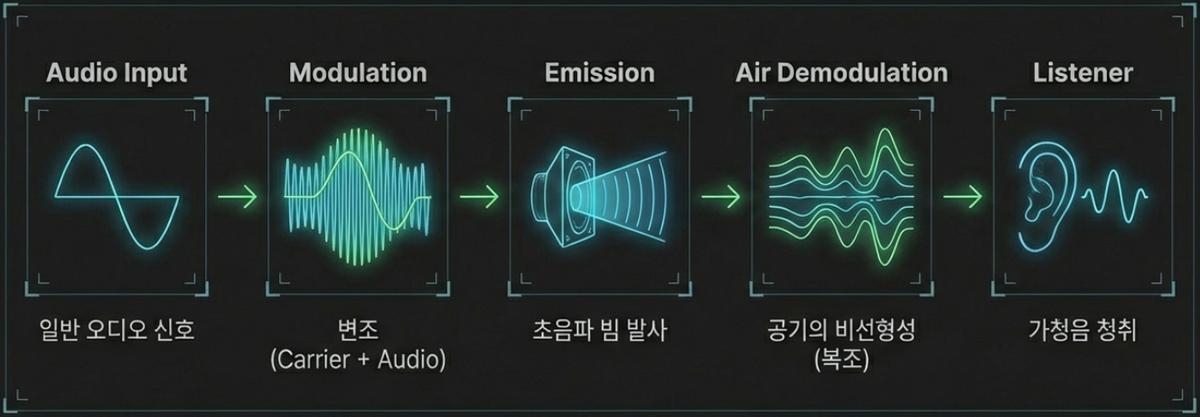
In Part 2 we said that a directional speaker carries audible speech on an ultrasonic wave. From this part onward we take the ingredients apart one by one. The first ingredient is, naturally, ultrasound — what exactly is it, what kinds are there, and how does it behave as a wave travelling through air?
Defining ultrasound — it is not simply "sound you cannot hear"
The textbook definition is simple: sound above the upper limit of human hearing, roughly 20kHz. But that is a negative definition written from the ear's point of view. Seen through an engineer's eyes, the essence lies elsewhere — ultrasound is not "inaudible sound" but "sound you can handle like light." As the wavelength shrinks, sound acquires the ability to travel in straight lines, to reflect, and to be focused, just as light does. The entire operation of a directional speaker rests on that property.
The 20kHz boundary is not a physical constant either; it is merely the statistical upper limit of human hearing. Nothing about air changes abruptly above or below it. The wave equation is the same, the speed of sound is the same, and the rules of reflection and diffraction are the same. Exactly one thing changes: the wavelength. And when the wavelength changes, everything you can do with that wave changes with it.
A map of the bands — there are floors above 20kHz too
"Ultrasound" lumps everything above 20kHz into one word, which makes it nearly useless in practice. In real design work, the medium, the components, and the applications all differ completely depending on which floor you are standing on. Listed together with wavelengths computed from a speed of sound of 343.2m/s in air at 20℃, the picture looks like this.
| Band | Frequency | Wavelength in air | Main medium | Typical use |
|---|---|---|---|---|
| Audible sound | 20Hz–20kHz | 17.2m–17.2mm | Air | Speech, music |
| Power and sensing ultrasound | 20–100kHz | 17.2–3.4mm | Air, liquid | Directional speakers, range sensors, cleaning |
| Mid-frequency ultrasound | 100kHz–1MHz | 3.4–0.34mm | Liquid, solid | Flow measurement, inspection of thick parts |
| Diagnostic band | 1–20MHz | (cannot propagate in air) | Human tissue | Ultrasound imaging, blood-flow measurement |
| Very high frequency | Above 20MHz | (cannot propagate in air) | Solids, thin films | Acoustic microscopy, high-resolution surface imaging |
The cells marked "cannot propagate in air" matter most. Evaluating the international standard formula (ISO 9613-1) for air at 20℃ and 50% relative humidity gives about 162dB/m at 1MHz. Ten centimetres costs you 16dB; one metre costs 162dB. That is precisely why diagnostic imaging, which works in the MHz range, presses the probe against the body and uses coupling gel. For high-frequency ultrasound, air is effectively a wall. The fact that directional speakers stay on the low floor of a few tens of kilohertz is therefore not a preference but a constraint.
Nature was using ultrasound first
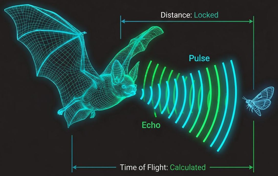
Ultrasound is not a human invention. A bat emits ultrasonic pulses and listens to the returning echo, computing distance from the time of flight. A guidance system precise enough to snatch a single insect out of the air inside a pitch-black cave runs on ultrasound. The underwater acoustic detection used by dolphins works on the same principle. Human ultrasonic engineering is, more than anything, a latecomer following nature's engineering.
That bats actually emit ultrasound was only confirmed experimentally in 1941. Until then the belief that "bats avoid obstacles by touch" had circulated for nearly 150 years. Without ultrasonic microphones there was simply no way to prove the existence of a signal that exists but cannot be heard.
Why a bat uses ultrasound in particular falls straight out of a calculation. For an echo-based system the range resolution is c·τ/2 for a pulse of length τ. A 1ms pulse gives 17cm of resolution — not enough to tell a moth from a leaf. Shorten the pulse to 0.1ms and the resolution becomes 1.7cm. But making a short pulse requires a correspondingly high frequency. A 1kHz tone fits only a tenth of a cycle into 0.1ms, whereas 40kHz fits four full cycles. High frequency permits short pulses, and short pulses buy fine range resolution — which is why bats work in the 20–200kHz band. For reference, the round-trip echo time for a target one metre away is 5.83ms, and human-made ultrasonic range sensors read exactly the same interval.
Kinds of ultrasound — longitudinal and shear waves
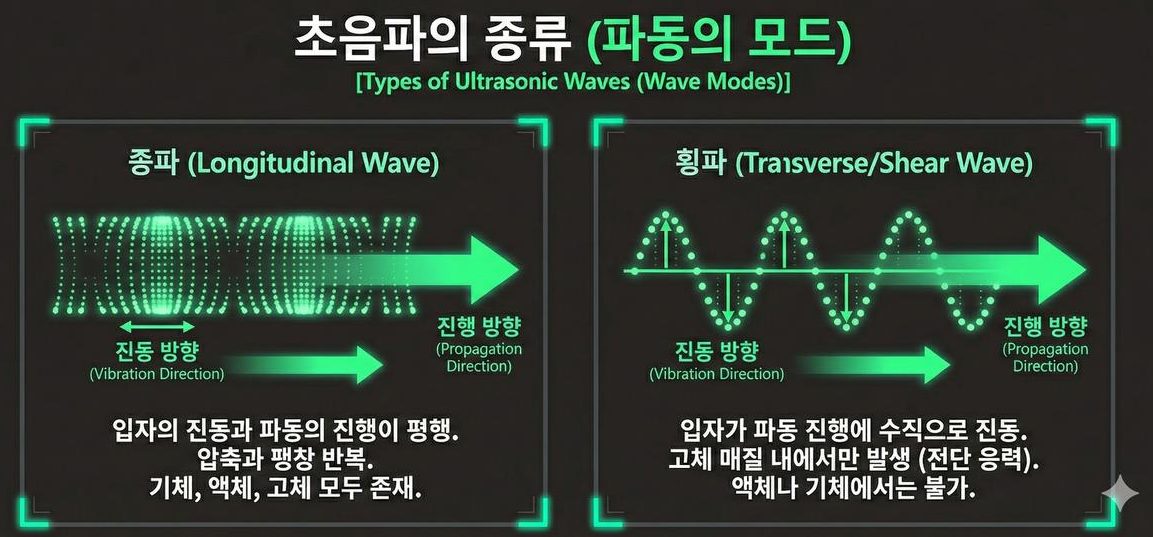
- Longitudinal wave — the particles oscillate parallel to the direction of travel. The wave advances through repeated compression and rarefaction, and it exists in gases, liquids, and solids alike. Every sound flying through air is a longitudinal wave.
- Transverse (shear) wave — the particles oscillate perpendicular to the direction of travel. Because shear stress is required, it occurs only in solid media and cannot exist in a liquid or a gas.
What separates the two is whether the medium resists shear deformation. A solid has a restoring force (the shear modulus) when its layers slide sideways, so it can carry a shear wave. In air and water that force is essentially zero: push sideways and the medium simply flows, and with no restoring force there is no shear wave. For the same reason longitudinal waves are faster than shear waves in a solid — compressional stiffness exceeds shear stiffness.
At the surface of a solid, or within a thin plate, longitudinal and shear motion mix and give rise to further modes such as surface waves and plate waves. What a directional speaker deals with in air is purely the longitudinal wave, but all of these modes appear inside the piezoelectric transducer we will cover later, which is a solid. Why an element resonates well only at a particular thickness and a particular shape is ultimately a story about these modes, so the distinction is worth learning early.
Propagation ① Reflection and transmission — impedance decides almost everything
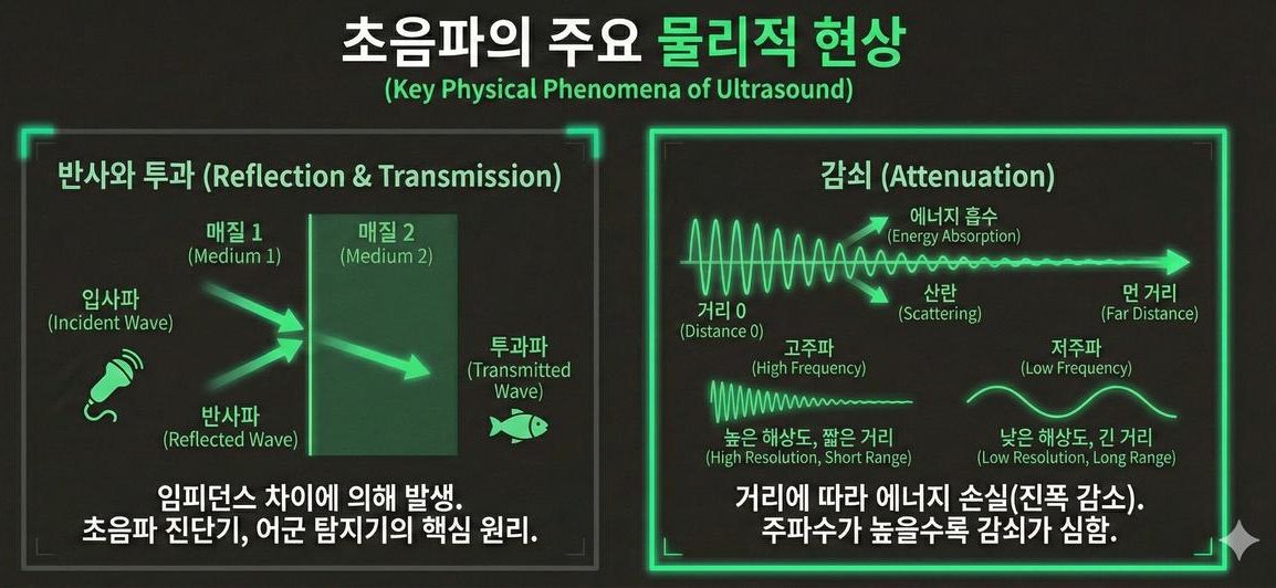
At the boundary between two different media, part of an ultrasonic wave is reflected and part is transmitted. The ratio is set by the acoustic impedance Z = ρc (density × speed of sound). For media of impedance Z₁ and Z₂ at normal incidence, the fraction of energy transmitted is 4Z₁Z₂/(Z₁+Z₂)², and everything else comes back.
The impedance of air at 20℃ is a mere 413 Rayl. Compared with other materials the gap is overwhelming.
| Medium | Acoustic impedance Z | Energy transmitted from air | In dB |
|---|---|---|---|
| Air (20℃) | 413 Rayl | reference | — |
| Water | 1.48 × 10⁶ Rayl | 0.112% | −29.5dB |
| Soft tissue | 1.63 × 10⁶ Rayl | 0.101% | −29.9dB |
| Aluminium | 1.70 × 10⁷ Rayl | 0.0097% | −40.1dB |
| Piezoelectric ceramic | 3.30 × 10⁷ Rayl | 0.0050% | −43.0dB |
| Steel | 4.54 × 10⁷ Rayl | 0.0036% | −44.4dB |
The table says two things. First, ultrasound barely crosses an air–solid boundary at all. More than 99.99% of a wave that strikes a wall comes straight back. That is why ultrasonic scanners and fish finders work, and equally why a directional beam that lands on a wall turns that spot into a new source scattering sound through the whole room. The physical basis for the line in Part 1 — "what you aim at is half the design" — is exactly this table.
Second, getting ultrasound out into the air is itself a hard problem. Radiating directly from piezoelectric ceramic into air passes 0.005% of the energy, that is, −43dB. An ultrasonic speaker built without countermeasures traps almost all of its electrical energy inside the element and dumps it as heat. Hence the matching layer of intermediate impedance. An ideal quarter-wave matching layer has the geometric mean of the two impedances, √(Z₁Z₂), which for air and piezoelectric ceramic is √(413 × 3.3×10⁷) ≈ 1.2×10⁵ Rayl. Materials with that value are rare in nature, so in practice designers use ultra-low-density porous materials such as foams and aerogels, or stack several matching layers. We meet this problem again in the transducer design of Part 10.
Propagation ② Attenuation — how fast air eats ultrasound
Even after crossing a boundary intact, an ultrasonic wave keeps shrinking as it advances. Two causes overlap.
- Spreading loss — the energy thins out over an ever larger area. It is independent of frequency, and concentrating the energy into a beam reduces it greatly.
- Absorption loss — the viscosity and thermal conduction of air, together with rotational and vibrational relaxation of oxygen and nitrogen molecules, convert acoustic energy into heat. It grows roughly with the square of frequency, and no amount of beamforming avoids it.
The second one sets the working range of a directional speaker. Evaluated with the international standard formula at 20℃, 50% relative humidity and one atmosphere, the numbers are as follows.
| Frequency | Wavelength | Absorption coefficient | Loss over 10m | Distance for amplitude to fall to 1/e |
|---|---|---|---|---|
| 1kHz | 343mm | 0.005dB/m | 0.05dB | 1,862m |
| 10kHz | 34.3mm | 0.159dB/m | 1.6dB | 54.7m |
| 20kHz | 17.2mm | 0.524dB/m | 5.2dB | 16.6m |
| 40kHz | 8.6mm | 1.318dB/m | 13.2dB | 6.6m |
| 60kHz | 5.7mm | 1.980dB/m | 19.8dB | 4.4m |
| 100kHz | 3.4mm | 3.280dB/m | 32.8dB | 2.6m |
| 200kHz | 1.7mm | 8.228dB/m | 82.3dB | 1.1m |
Here the great principle of ultrasonic engineering — the higher the frequency, the finer the resolution but the shorter the reach — is confirmed numerically. The absorption difference between 1kHz and 200kHz exceeds a factor of 1,600. Directional speakers settled near 40kHz because that is the middle of this table, the compromise between straightness and reach.
What designers often miss — absorption depends on the weather
The absorption coefficient is not a fixed constant. At the same 40kHz, feeding different conditions into the same formula changes it by nearly a factor of three. At 20℃ it is 0.456dB/m at 10% relative humidity, 1.068dB/m at 30%, worst at 1.326dB/m around 55%, then easing back to 1.173dB/m at 90%. Drop the temperature to 0℃ and it falls to 0.450dB/m. Converted to a 10m path that is the difference between 4.5dB and 13.3dB — the same hardware losing more than 8dB depending on conditions.
The reason absorption peaks in the middle rather than rising monotonically with humidity is that water molecules accelerate the vibrational relaxation of oxygen molecules, creating an absorption peak. That peak happens to fall right in the humidity range people find comfortable. This is why a permanently installed indoor unit must be given sound-pressure headroom based on the worst case, and why a device that sounded clear in a dry winter room turns muffled in the rainy season.
Near field and far field — a beam is not a beam from the start
An ultrasonic beam is usually drawn like the cone of a torch, but the real field splits into two regions. Immediately in front of the radiating face, waves from different points on that face arrive out of phase and the sound pressure fluctuates violently. That region is the near field, and for a circular radiator of diameter D its length is roughly D²/(4λ). Some texts instead place this boundary at the Rayleigh distance πD²/(4λ), about 3.14 times further under the same conditions — parts 7 and 8 use that convention. Beyond it, pressure falls smoothly in inverse proportion to distance and the directivity pattern stabilises.
| Aperture D (at 40kHz) | −3dB beam width | Near-field length |
|---|---|---|
| 50mm | 10.1° | 0.07m |
| 100mm | 5.1° | 0.29m |
| 200mm | 2.5° | 1.17m |
| 300mm | 1.7° | 2.62m |
| 500mm | 1.0° | 7.28m |
Beam width was computed from the −3dB half-power approximation for a uniform circular radiator, θ ≈ 59° × λ/D, and near-field length from D²/(4λ). The trade-off visible in the table is the heart of the design problem — enlarging the aperture sharpens the beam, but it also pushes the distance at which the field settles down further away. A 500mm panel produces a razor-sharp 1° beam, yet everything within 7m sits in a region of erratic pressure, which actually hurts close-range listening. Fix the listening distance first, then choose the aperture.
Ultrasound is not a radio wave
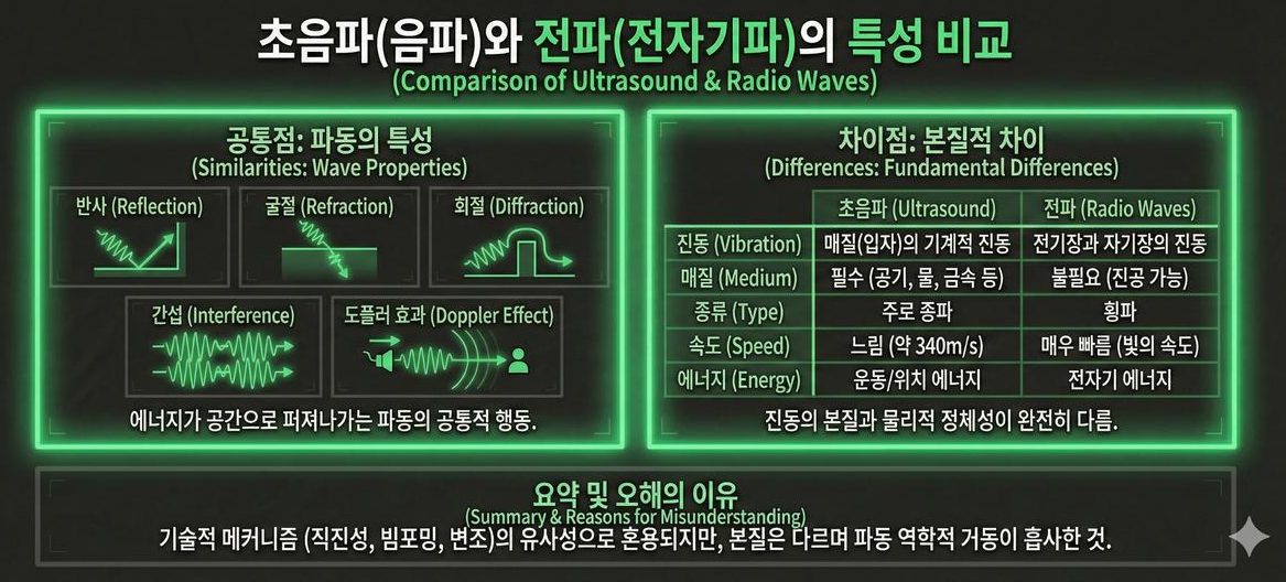
Ultrasound and radio are frequently confused because both exhibit the common behaviours of waves: reflection, refraction, diffraction, interference, and the Doppler effect. Their nature is nevertheless different. Ultrasound is mechanical vibration of a medium — air, water, metal — while a radio wave is oscillation of electric and magnetic fields and therefore travels through vacuum. Their speeds, roughly 340m/s against the speed of light, are not even comparable.
| Item | Ultrasound (sound wave) | Radio (electromagnetic wave) |
|---|---|---|
| What oscillates | Position of medium particles | Electric and magnetic fields |
| Propagation in vacuum | Impossible | Possible |
| Speed | About 343m/s (air at 20℃) | About 3×10⁸ m/s |
| Wavelength (at 40kHz / 40MHz) | 8.6mm | 7.5m |
| Attenuation in air | Very large (1.3dB/m at 40kHz) | Very small |
| Fundamental mode | Longitudinal (shear too, in solids) | Transverse only |
The last two rows split the character of the two technologies. Heavy attenuation means ultrasound does not travel far, but turn that around and it means a signal that vanishes a few metres away, so the same band can be reused in the next room with no interference. The low speed is not purely a drawback either — the short wavelength lets millimetre-scale structures form a beam, and time-of-flight ranging becomes possible with inexpensive circuitry.
Part 2 used the radio analogy of "putting speech on a carrier." The analogy holds because the modulation and beamforming mechanisms of the two waves resemble each other, not because they are the same wave. The equations share a form; the physical reality does not.
Common misconceptions and limits
- "Ultrasound has no effect on people at all." Not accurate. Several countries maintain broadly similar exposure guidance for airborne ultrasound above 20kHz, but researchers have pointed out that the human studies underpinning those limits rest on very small samples and deserve re-examination. On top of that, the upper limit of hearing varies greatly between individuals and with age, so for some people a 20kHz signal really is audible. That is why exposure level and installation distance must be set together during design.
- "Raising the frequency always makes things better." The beam narrows, but absorption grows roughly with the square of frequency. Going from 40kHz to 80kHz halves the beam width while doubling absorption from 1.32dB/m to 2.61dB/m. Which side wins is decided by the target distance.
- "Ultrasound passes through walls easily." The exact opposite. As the impedance table showed, more than 99.99% is reflected at an air–solid boundary. Ultrasound never carries through a wall to be heard on the other side, and because absorption accumulates with distance, the strongest point is always right in front of the radiating face.
Summary
Ultrasound is sound above 20kHz, and thanks to its short wavelength it is sound you can handle like light. In air it travels as a longitudinal wave, is reflected almost entirely at an impedance boundary, and grows more precise but decays faster as frequency rises. That decay swings by up to a factor of three with the weather, and the distance at which the beam settles grows with the square of the aperture. Four numerical intuitions — −43dB of impedance mismatch, 1.3dB/m of absorption, a beam width of 59°λ/D, and a near field of D²/4λ — will keep reappearing in the parts that follow.
The next part covers why these properties favour a directional speaker, and how ultrasound is actually generated in the first place.
Series guide
"The Science of Directional Speakers" continues in the following order.
- What is a directional speaker — a flashlight for sound
- Putting sound on sound you cannot hear — first steps in the operating principle
- Applications of directional speakers — exhibitions, safety, retail, offices
- What is ultrasound — definition, types, propagation (this part)
- Coming up: why ultrasound, the parametric acoustic array (PAA), beamforming, piezoelectric transducers, Nyquist, modulation, signal processing
This series is a blog-format reworking of self-produced lecture material in which ultrasonic directional audio technology was researched and organised first-hand. The figures are taken from that material.
References
- H. E. Bass et al., "Atmospheric absorption of sound: Further developments," JASA 97(1), 680 (1995) : source of the formula behind the absorption table (0.005 at 1kHz, 1.318 at 40kHz, 8.228dB/m at 200kHz) and the humidity/temperature dependence — the paper underlying international standard ISO 9613-1
- O. Cramer, "The variation of the specific heat ratio and the speed of sound in air with temperature, pressure, humidity, and CO₂ concentration," JASA 93(5), 2510 (1993) : basis for the 343.2m/s speed of sound at 20℃ and the wavelength calculations
- D. R. Griffin & R. Galambos, "The sensory basis of obstacle avoidance by flying bats," J. Exp. Zool. 86(3), 481 (1941) : the original paper that experimentally established bats' use of ultrasound
- W. W. L. Au & J. A. Simmons, "Echolocation in dolphins and bats," Physics Today 60(9), 40 (2007) : overview of the frequency bands and pulse design used by bats and dolphins
- T. E. Gómez Álvarez-Arenas, "Acoustic impedance matching of piezoelectric transducers to the air," IEEE TUFFC 51(5), 624 (2004) : the piezoelectric–air impedance gap and matching-layer design — basis for the −43dB figure and the geometric-mean matching impedance
- T. G. Leighton, "Are some people suffering as a result of increasing mass exposure of the public to ultrasound in air?," Proc. R. Soc. A 472, 20150624 (2016) : argues that the evidence base for airborne ultrasound exposure guidance is thin
- T. G. Leighton, "Public Exposure to Airborne Ultrasound and Very High Frequency Sound," Acoustics Today 16(3), 17 (2020) : summary of individual and age variation in the hearing limit and the state of ultrasound exposure standards
- P. J. Westervelt, "Parametric Acoustic Array," JASA 35(4), 535 (1963) : the theoretical starting point of the whole series — treated in depth in Parts 6 and 7
- Acoustic impedance — Wikipedia : definition of Z = ρc and the reflection/transmission coefficients
- Near and far field — Wikipedia : near-field length D²/4λ and the far-field condition
- Animal echolocation — Wikipedia : overview of echolocation in bats and dolphins