Part 4 set out what ultrasound is. The question in this part is one step more practical — of all the sounds available, why use ultrasound in particular? And how is that ultrasound actually produced? Once you know the answer, roughly half of a directional speaker's design starts to become readable.
Reason 1 — Straightness: the shorter the wavelength, the less sound spreads
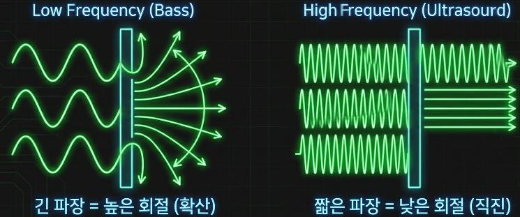
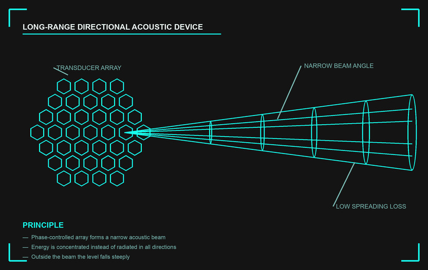
When a wave meets an obstacle or an opening it bends and spreads out — diffraction. The degree of diffraction is set by the wavelength. Bass with a wavelength of several metres spreads in all directions the moment it leaves the speaker, whereas ultrasound with a wavelength of a few millimetres diffracts little and travels straight in a narrow beam. The "flashlight for sound" of Part 1 comes out of this physics.
Put in numbers, it looks like this. The −3dB beam width of a circular radiator of diameter D is approximately θ ≈ 59° × λ/D. What decides the outcome is neither D nor λ alone but the ratio between them. Hand someone the same 300mm panel and the result changes completely depending on the frequency you drive it with.
θ ≈ 59° × λ / D (−3dB half-power approximation for a uniform circular radiator)
Feed 500Hz into a 300mm panel and D/λ is only 0.44, so the word "beam" does not even apply — the radiation is effectively omnidirectional. Feed the same panel 5kHz and you get 13.5°, at 20kHz 3.4°, and at 40kHz 1.7°. A plate you can cover with one hand produces something close to a laser pointer. The fact that there is no way to improve that number other than shortening the wavelength is the first reason ultrasound was chosen.
Reason 2 — Size: a beam you can build into a realistic device
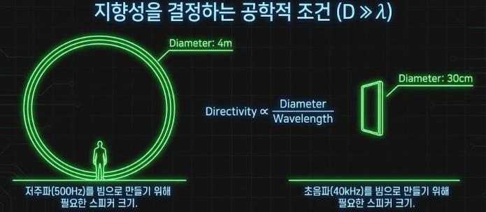
To turn sound into a beam, the size of the source (D) must be sufficiently larger than the wavelength (λ) — directivity scales as D/λ. Making a beam out of 500Hz bass demands a gigantic speaker four metres across, while for 40kHz ultrasound with its short wavelength a panel 30cm across is enough. The moment you switch to ultrasound, a "sound beam" shrinks to the size of a desktop device.
Inverting that statement with the formula above sharpens the design intuition considerably. Fix the target beam width and solve for the required aperture: D = 59° × λ / θ. For two target beam widths the numbers come out as follows.
| Frequency | Wavelength in air | Aperture for a 30° beam | Aperture for a 10° beam |
|---|---|---|---|
| 100Hz | 3.43m | 6.75m | 20.2m |
| 500Hz | 686mm | 1.35m | 4.05m |
| 1kHz | 343mm | 0.68m | 2.03m |
| 4kHz | 85.8mm | 169mm | 506mm |
| 20kHz | 17.2mm | 34mm | 101mm |
| 40kHz | 8.6mm | 17mm | 51mm |
| 100kHz | 3.4mm | 7mm | 20mm |
The top three rows are the reason a directional speaker cannot be built out of audible sound. Around 500Hz, where the substance of the human voice sits, a 10° beam needs a radiating face four metres in diameter. That might work on the side of a building, but not on an exhibition ceiling or an office desk. At 40kHz, by contrast, 51mm of diameter gives the same 10° beam. In terms of area that is 6,300 times smaller. Real products use panels around 30cm across not to narrow the beam further, but largely because more elements are needed to secure the sound pressure and low-frequency headroom discussed later.
Reason 3 — It has to be inaudible to serve as a tool
Judging by straightness and size alone, one question remains: "16kHz, just below the hearing limit, already has a fairly short wavelength — why won't it do?" Here the third reason appears. In a directional speaker, ultrasound is a means of carriage, not the content. As Part 2 showed, what must arrive at the ear is the audible component that the air demodulates for itself; the carrier must remain unheard to the very end. If the carrier were audible, the listener would hear a piercing tone layered over everything, and the technique would collapse.
The carrier therefore has to climb into a band people definitely cannot hear. And as Part 4 noted, the upper hearing limit varies substantially between individuals and with age, so choosing something around 20kHz with no margin leaves a risk that some listeners will hear it. Placing the carrier near 40kHz has one further motive: safety margin against the hearing limit.
The side benefits are large as well. The ultrasonic band is a quiet band with almost no human-made noise, and per the absorption table in Part 4 it disappears by itself after a few metres. As a result the same carrier can be reused in the neighbouring zone with no mutual interference. What would demand a channel plan in radio is solved for you by the absorption of air.
Were there alternatives? Other ways of concentrating sound
Attempts to concentrate sound in one direction long predate ultrasound. Comparing what each approach gives and what it gives up makes the position of the parametric method clear.
| Approach | Principle | Condition for good directivity | Limitation |
|---|---|---|---|
| Parabolic reflector | A reflecting surface aligns the wavefront | Reflector diameter ≫ wavelength | The lower the band, the more enormous the reflector. Diffraction remains |
| Line array | A vertical stack narrows only the vertical plane | Array length ≫ wavelength | Horizontal coverage stays wide. No left–right separation |
| Audible phased array | Phase differences across many drivers steer a beam | Overall array size ≫ wavelength | Wideband, so beam width varies with frequency; the low end never narrows |
| Inverted supercardioid principle | Differential radiation using a pressure gradient | Element spacing ≪ wavelength | Radiation efficiency collapses, making sound pressure hard to obtain |
| Parametric array | Air generates audible sound inside an ultrasonic beam | Carrier wavelength ≪ radiator size | Low conversion efficiency and weak low end. Distortion must be managed |
The first four share one thing: they all tried to win using audible wavelengths. None of them escapes the fundamental condition that λ is large, so there was no answer beyond making the device bigger. Only the parametric approach changes the board — because it separates the wavelength that forms the beam from the wavelength people hear. The beam is made with an 8.6mm wavelength; the sound is heard at metre-scale wavelengths. That is the real meaning of the nonlinear acoustics covered in Part 6.
How ultrasound is produced — three stages of generation and radiation
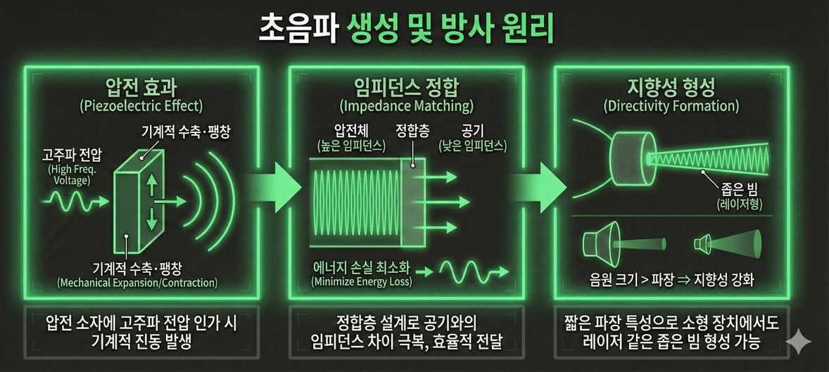
- Piezoelectric effect — apply a high-frequency voltage to a piezoelectric element and it contracts and expands mechanically at that frequency. This is the heart where an electrical signal becomes sound.
- Impedance matching — the hard piezoelectric body and soft air differ enormously in impedance, so left alone most of the energy is reflected at the boundary. A matching layer in between minimises the loss.
- Directivity formation — thanks to the short wavelength, even a compact device satisfies the condition source size > wavelength and produces a laser-like narrow beam.
Why stage two is so hard is already told by the impedance table in Part 4. Radiating directly from piezoelectric ceramic into air passes only 0.005% (−43dB) of the energy. An ideal quarter-wave matching layer has the geometric mean of the two impedances, and its thickness is set by the speed of sound inside that layer ÷ frequency ÷ 4. At 40kHz a low-density material with a speed of 500m/s calls for 3.1mm, one with 1,000m/s for 6.3mm. Matching-layer design is therefore a problem of hitting the material impedance and the thickness at the same time, and the rarity of materials that satisfy both is the long-standing difficulty of air-coupled ultrasound.
The piezoelectric effect of stage one is covered in depth in Part 9, and element design in Part 10.
The lineage of transduction — piezoelectric, magnetostrictive, electrostatic
Piezoelectricity is not the only way to turn electricity into mechanical vibration. Across a century of ultrasonic engineering, four transduction methods have seen real use.
| Method | Physics | Strengths | Weaknesses | Typical use |
|---|---|---|---|---|
| Piezoelectric | Electric field deforms a crystal lattice | High efficiency, works up to high frequencies, easy to miniaturise | Hard ceramic couples poorly to air. Temperature and voltage dependent | Airborne sensors, directional speakers, diagnostic probes |
| Magnetostrictive | Magnetic field deforms a ferromagnetic body | Large force and high power density. Mechanically robust | Drive coil and magnetic circuit are bulky and lossy. Poor at high frequency | High-power underwater sources, ultrasonic machining and welding |
| Electrostatic (capacitive) | Electrostatic force between electrodes drives a thin membrane | Light membrane couples well to air. Wide bandwidth | Needs a high bias voltage; sound pressure is low | Air-coupled measurement, micromachined devices |
| Electrodynamic | Force on a current-carrying conductor in a magnetic field | Simple structure, favourable at low frequency | Heavy moving mass, efficiency collapses above tens of kHz | Audible loudspeakers, low-frequency sources |
Why piezoelectric ceramic became the standard
Early sonar used natural quartz and magnetostrictive metals. What changed the picture was the lead zirconate titanate family of piezoelectric ceramics that emerged in the 1950s. These could be sintered into any desired shape, given piezoelectricity by poling, and tuned in their properties by adjusting composition. Compared with an era of cutting natural crystals, the decisive step was bringing the material itself into the set of design variables.
The victory of ceramics comes at a price, however. As the Part 4 table showed, the impedance of piezoelectric ceramic is 3.30 × 10⁷ Rayl, eighty thousand times that of air. The instant it meets air, 43dB vanishes, so in air-coupled ultrasound the matching layer, the resonant structure, and the horn matter as much as the element itself. Electrostatic devices, conversely, couple naturally well to air because the membrane is light, but struggle to produce high sound pressure. The efficient one does not suit air; the one that suits air is weak — that trade-off is the starting point of transducer design.
140 years of history — from detection to control
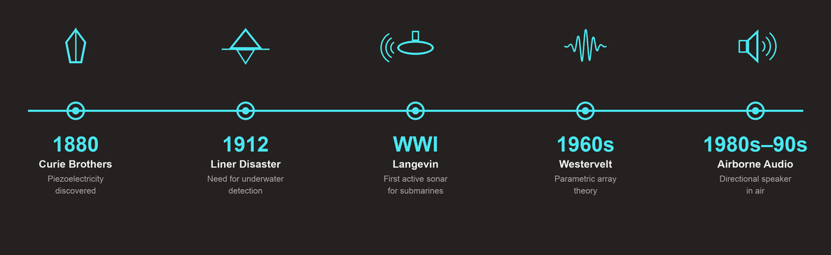
In 1880 the Curie brothers discovered the piezoelectric effect, and in 1912 the sinking of a large passenger liner in the North Atlantic brought home the need for underwater detection. During the First World War the French physicist Langevin built the first sonar to detect submarines, and modern ultrasonic engineering began. In the 1960s Westervelt established the theory of the parametric acoustic array, and in the late 1990s work applying it in earnest to airborne audio reproduction gave birth to today's directional speaker. The thread can be stated in one line — a technology for "detecting" the invisible evolved into a technology for "controlling" sound.
Looked at more closely, ultrasonic engineering passed through three leaps.
- First — securing a means of transmission (1880 to the 1950s). The discovery of piezoelectricity and the arrival of piezoelectric ceramics made it possible to generate ultrasound at a chosen frequency and a chosen intensity. Up to this point ultrasound was a detection tool: send and receive.
- Second — securing the theory (1960s). It was established theoretically that a strong ultrasonic beam generates new frequencies inside itself. The parametric array theory of 1963 is the starting point, and in 1965 came the self-demodulation relation stating that the low-frequency component produced by the beam is proportional to the second time derivative of the squared envelope — the same expression met in Part 2.
- Third — transplantation into air (1980s onward). For nearly twenty years after the theory appeared, the parametric array remained an underwater story. A report of actually producing audible sound in air arrived in 1983, beginning the lineage that leads to today's directional speakers. In the late 1990s a series of patents improving the modulation scheme and element arrangement moved the field toward commercialisation.
Why water came first is explained by the nonlinearity discussion of Part 2. Water has a larger nonlinearity parameter than air and far lower attenuation, which secures a long interaction distance. Air, conversely, has a small ρc³ and therefore produces far more distortion for the same sound pressure, but its heavy attenuation shortens the interaction region. The tug of war between these two properties is the subject of Parts 6 and 7.
An application map — where ultrasound goes to work
The same physics wears a different face in each field.
- Medicine and aesthetics — diagnostic imaging (high resolution at 2MHz and above), non-invasive treatment using high-intensity focused ultrasound (HIFU), skin lifting.
- Industry and safety — non-destructive testing (NDT) of aircraft parts and pipelines, ultrasonic cleaning using cavitation bubbles, Doppler-based flow measurement.
- Defence and security — sonar that hunts submarines, long-range directional hailing devices that carry a warning announcement over distance, zone security announcements audible only to an intruder at a particular spot.
Why the frequency differs from application to application
The frequency each field settled on is not a matter of taste but something forced by the medium and the target resolution. Compute wavelengths from the speed of sound in each medium and lay them side by side, and the rule becomes visible at a glance.
| Application | Typical frequency | Medium | Wavelength in that medium | Physics exploited |
|---|---|---|---|---|
| Directional speaker | 40kHz | Air | 8.6mm | Nonlinear self-demodulation plus suppressed diffraction |
| Range sensor | 40kHz | Air | 8.6mm | Round-trip time of flight (5.83ms per metre) |
| Ultrasonic cleaning | 20–100kHz | Water, cleaning fluid | 37mm (at 40kHz) | Growth and collapse of cavitation bubbles |
| Metal non-destructive testing | 1–10MHz | Steel, aluminium | 1.18mm (steel, 5MHz) | Reflection at a defect boundary |
| Abdominal diagnostic imaging | 2–5MHz | Soft tissue | 0.31mm (at 5MHz) | Backscatter from tissue impedance contrast |
| Superficial and ophthalmic imaging | Above 20MHz | Soft tissue | 0.077mm (at 20MHz) | Same, restricted to shallow depth |
| Focused therapy (HIFU) | 0.5–5MHz | Soft tissue | 0.31–3.1mm | Heat accumulation and mechanical action at the focus |
The principle running through the table is the combination of two statements confirmed in Part 4. Resolution is tied to wavelength, and reach is tied to absorption. Imaging therefore pushes toward shorter wavelengths — higher frequencies — and sacrifices depth. That is why superficial imaging, which only looks at shallow structures, uses 20MHz while deep abdominal work stays at 2–5MHz. Airborne applications run the opposite way, hitting the absorption wall and being pushed down below a few tens of kilohertz. Cleaning points in yet another direction — the goal is not fineness but growing bubbles, so the frequency is lowered to give the bubbles time to grow.
And the newest region on this map is our own subject, the directional speaker. The next part enters the heart of the series, the parametric acoustic array (PAA) — the world of nonlinear acoustics in which "the air becomes the speaker."
Common misconceptions and limits
- "Using ultrasound makes sound travel further." The opposite. Per the absorption table in Part 4, 40kHz loses 1.3dB every metre. A directional speaker seems to be audible at a distance because the energy is packed into a narrow angle and spreading loss is small, not because absorption is small. The two losses are separate: ultrasound gains on one and loses on the other.
- "Make the piezoelectric element bigger and the output grows proportionally." A larger radiating area does raise acoustic output, but the impedance gap with air is unchanged. Enlarging area without a matching structure enlarges the wasted heat along with it. Adding elements is a decision that increases output, heat, and drive-circuit burden simultaneously.
- "Magnetostriction is powerful, so it must be good for speakers too." Magnetostrictive devices deliver large forces, but the mass and loss of the magnetic circuit make efficiency deteriorate sharply in the tens of kilohertz. It is a material for low-frequency, high-power applications that need force, not for a beam of tens of kilohertz in air.
- "It is inaudible, so any intensity is fine." As Part 4 pointed out, exposure guidance for airborne ultrasound has been criticised for resting on a thin base of human studies. Being inaudible is closer to having no warning signal than to having no effect. Installation distance and output must be decided together.
Summary
The reasons for using ultrasound come in three layers. The short wavelength suppresses diffraction (straightness); that in turn lets a device of realistic size form a beam (size); and being inaudible to people lets it remain purely a means of carriage (transparency). The third matters most — in a directional speaker, ultrasound is not a sound to be heard but a vessel that delivers sound.
Producing that ultrasound consists of three stages: converting electricity to vibration (piezoelectricity), handing that vibration over to air (matching), and raising a beam with the short wavelength (directivity). The fact that 43dB hangs on the second stage defines the efficiency of the whole technology, and it is hardly an exaggeration to say that getting over that wall is the entirety of transducer design. The next part covers how the ultrasound thus launched creates sound by itself inside the air.
Series guide
"The Science of Directional Speakers" continues in the following order.
- What is a directional speaker — a flashlight for sound
- Putting sound on sound you cannot hear — first steps in the operating principle
- Applications of directional speakers — exhibitions, safety, retail, offices
- What is ultrasound — definition, types, propagation
- Why ultrasound — generation principles and an application map (this part)
- Coming up: the parametric acoustic array (PAA), beamforming, piezoelectric transducers, Nyquist, modulation, signal processing
This series is a blog-format reworking of self-produced lecture material in which ultrasonic directional audio technology was researched and organised first-hand. The figures are taken from that material.
References
- B. Jaffe, R. S. Roth & S. Marzullo, "Piezoelectric Properties of Lead Zirconate-Lead Titanate Solid-Solution Ceramics," J. Appl. Phys. 25(6), 809 (1954) : the original report on the properties of lead zirconate titanate piezoelectric ceramics — basis for the statement that material became a design variable
- "Magnetostrictive ultrasonic transducer," Ultrasonics 10(6), 287 (1972) : structure and characteristics of magnetostrictive transducers — basis for that row of the transduction comparison table
- "Advances in air-coupled ultrasonic transducers," Nondestructive Testing and Evaluation 12(3), 155 (1995) : the impedance problem of air-coupled ultrasound and matching and electrostatic approaches — basis for stage two of the three stages
- T. E. Gómez Álvarez-Arenas, "Acoustic impedance matching of piezoelectric transducers to the air," IEEE TUFFC 51(5), 624 (2004) : impedance and thickness design of piezoelectric-to-air matching layers — basis for the quarter-wave calculation
- P. J. Westervelt, "Parametric Acoustic Array," JASA 35(4), 535 (1963) : the original paper on parametric array theory — the "second leap" of the history section
- H. O. Berktay, "Possible exploitation of non-linear acoustics in underwater transmitting applications," J. Sound Vib. 2(4), 435 (1965) : the relation stating that self-demodulation follows the second derivative of the squared envelope
- M. Yoneyama et al., "The audio spotlight: An application of nonlinear interaction of sound waves to a new type of loudspeaker design," JASA 73(5), 1532 (1983) : the first report of producing audible sound with a parametric array in air — the "third leap"
- US 5,889,870 — Acoustic heterodyne device and method (1999) : a late-1990s patent improving the modulation and drive scheme
- V. S. Dogra, M. Zhang & S. Bhatt, "High-Intensity Focused Ultrasound (HIFU) Therapy Applications," Ultrasound Clinics 4(3), 307 (2009) : frequency bands and mechanisms of HIFU — basis for that row of the application map
- H. E. Bass et al., "Atmospheric absorption of sound: Further developments," JASA 97(1), 680 (1995) : the source of the formula behind the air absorption figure quoted here (1.3dB/m at 40kHz)
- Magnetostriction — Wikipedia : definition of magnetostriction and an overview of representative materials