It is time to keep the promise made in Part 2. We now take on the heart of the directional speaker — the parametric acoustic array (PAA). This part establishes the physics behind the phrase "the air becomes the speaker"; the next part confirms it with equations.
An accident in London, 1951 — Westervelt's discovery
In London in 1951, the physicist Peter J. Westervelt observed unintended audible frequencies appearing between powerful ultrasonic beams. Audible sound was being born at the place where two supposedly inaudible ultrasonic waves met. He applied Lighthill's equation, a foundation of fluid dynamics, to build a theory of acoustic scattering in a nonlinear medium, and that theory became the basis of both the modern ultra-directional speaker and underwater sonar. The "1960s Westervelt" entry on the timeline in Part 5 is this story.
The equation Lighthill formulated in 1952 was originally meant to explain why a jet engine makes noise. Its central idea is to rewrite the motion of a fluid as an "acoustically equivalent source." A region where fluid moves violently is replaced by a distribution of virtual sources sitting inside an otherwise quiet medium. What Westervelt did was substitute, in place of turbulence, the pressure field created by a strong ultrasonic beam. A tool built to solve aircraft noise became the theoretical foundation of the directional speaker.
At the time the idea ran against common sense. The basic premise of acoustics was the superposition principle — sounds pass through one another and do not change one another — and claiming that two sounds meet and give birth to a third directly denied that premise. What Westervelt's theory does is quantify when, and by how much, that exception occurs.
The two faces of air — linear and nonlinear
The key to understanding PAA is that air behaves differently depending on the magnitude of the sound energy.
- Linearity — predictable calm. When sound energy is small, air conveys the input signal in strict proportion with no distortion. Most of the sound we hear lives in this regime, and here multiple sounds can overlap without altering each other (superposition).
- Nonlinearity — distortion under strong energy. When the sound pressure becomes extreme, compression and rarefaction of air are no longer symmetric. The waveform distorts, and frequency components that were never there are born.
The second regime, which "breaks" the superposition principle traditional acoustics relied on, is the stage on which PAA performs. One point is easy to misunderstand, though — linear and nonlinear are not two different kinds of air. Air is always nonlinear; it merely looks linear when the sound pressure is low enough that the nonlinear term is negligible. Even at the 60dB of ordinary conversation the nonlinear component exists. It is simply far too small for anyone to notice.
Why nonlinearity arises — the speed of sound rides on amplitude
The reason a waveform distorts is remarkably simple: different parts of the sound travel at different speeds. There are two contributions.
- Nonlinearity of the medium itself (the equation-of-state term) — compressing air raises not only its density but also its stiffness. A compressed region becomes harder than before, and the speed of sound there rises.
- The convective term — the air particles in a compressed region are physically pushed along in the direction of travel. A wave riding on top of them is running on a "moving floor," so its speed relative to the ground gains that much.
Combining the two, the local speed of sound at a point is written as follows.
c(u) = c₀ + β·u (u = particle velocity, β = coefficient of nonlinearity, β ≈ 1.2 in air)
Here β comes from the equation of state of the medium; for air, B/A ≈ 0.4 gives β = 1 + B/2A ≈ 1.2. Working out how large the effect actually is makes the picture concrete. Since particle velocity is u = p/(ρ₀c₀), sorting by sound pressure level gives the following.
| Sound pressure level | Pressure p | Particle velocity u | Speed change β·u | Change relative to c₀ |
|---|---|---|---|---|
| 120dB | 20.0Pa | 0.048m/s | 0.058m/s | 0.017% |
| 130dB | 63.2Pa | 0.153m/s | 0.184m/s | 0.054% |
| 140dB | 200.0Pa | 0.484m/s | 0.581m/s | 0.169% |
| 150dB | 632.5Pa | 1.531m/s | 1.837m/s | 0.535% |
What deserves attention is how absurdly small the change is. Even at an extreme 140dB the difference in sound speed is only 0.17%. The waveform still distorts noticeably because that minute speed difference keeps accumulating along the path. If a crest runs just slightly faster than a trough over several metres, the crest gradually catches up with the trough ahead of it and the leading face of the waveform grows steeper. This is waveform steepening.
From steepening to shock — the distortion that distance builds
When steepening runs to completion the leading face becomes nearly vertical, a condition called shock formation. The distance at which the first shock forms is estimated from the following relation.
x̄ = ρ₀c₀³ / (β · ω · p₀) (ω = 2πf, p₀ = pressure amplitude)
The expression says three things: the higher the sound pressure, the higher the frequency, and the larger the nonlinearity coefficient, the closer the shock forms. Evaluating it in air at 40kHz for a range of pressures gives the table below. The absorption length listed alongside comes from the absorption coefficient of 1.318dB/m in Part 4 (the distance over which amplitude falls to 1/e is 6.59m).
| Level (40kHz) | Shock formation distance x̄ | Ratio to absorption length | Interpretation |
|---|---|---|---|
| 120dB | 8.07m | 0.82 | Absorption removes the wave before a shock forms |
| 125dB | 4.54m | 1.45 | Borderline — only weak distortion accumulates |
| 130dB | 2.55m | 2.58 | Practical regime — ample nonlinearity, waveform still gentle |
| 140dB | 0.81m | 8.17 | Strong nonlinearity — distortion already near the radiating face |
| 150dB | 0.26m | 25.83 | Saturation — energy leaks into harmonics |
The ratio in the third column is an indicator called the Gol'dberg number, which measures whether nonlinearity or absorption wins. Below one, air eats the energy before the distortion can grow; above one, the distortion is given time to develop. This is why a parametric speaker demands sound pressures around 130dB. The point is not to be loud but to enter the regime where nonlinearity beats absorption, because only there does air act as a demodulator.
The same table also states the ceiling of the technique. Push the pressure without limit and the shock forms right in front of the radiating face, after which energy leaks not into the difference frequency we want but into the harmonics. Hitting harder does not keep making things better. Nonlinearity grows the components you want and the ones you do not, indiscriminately.
Self-demodulation — the air restores the sound by itself
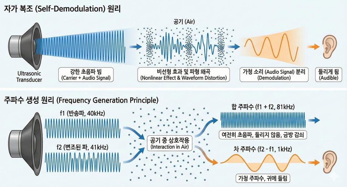
Concrete numbers dispel the magic. When a transducer strongly emits two ultrasonic waves — a carrier at f1 = 40kHz and a modulated wave at f2 = 41kHz — the two interact inside nonlinear air and new frequencies appear.
- Sum frequency (f1+f2 = 81kHz) — still ultrasonic. Inaudible, and being high in frequency it attenuates and vanishes quickly.
- Difference frequency (f2−f1 = 1kHz) — an audible frequency. Sound the ear can hear is born in the middle of the air.
Emit ultrasound modulated by a speech signal and this difference-frequency component becomes the original speech. The speaker does not make the sound; the air self-demodulates the ultrasound and reproduces it. This is the identity of the phenomenon that Part 2 explained only by intuition.
In reality, though, more than two components are born. Second-order nonlinearity corresponds to a product of the two signals, so every combination appears at once. Sorting out what emerges under the conditions above gives the following.
| Component | Frequency | Audible? | Fate |
|---|---|---|---|
| Difference (f2−f1) | 1kHz | Yes | The signal we want — barely absorbed, travels far |
| Sum (f1+f2) | 81kHz | No | Heavy absorption, dies quickly |
| Second harmonic (2f1) | 80kHz | No | Same — a loss from the carrier's energy |
| Second harmonic (2f2) | 82kHz | No | Same |
| Original carriers (f1, f2) | 40 and 41kHz | No | Decay at 1.3dB per metre while continuously feeding the virtual sources |
The structure the table reveals is the core of the technique. Of everything generated, only the difference frequency survives. All the rest sit in the ultrasonic band, where air absorbs them rapidly. In other words, air both creates the sound and acts as a low-pass filter that strips away the unwanted components. The designer need not fit a filter; the medium tidies up on its own.
The virtual end-fire array — an invisible speaker several metres long

So why does sound made this way travel so narrowly? The nonlinear interaction occurs continuously along the entire path the beam takes. The several-metre column of air through which the ultrasonic beam passes becomes, in its entirety, a virtual source column. In acoustics, a structure with sources lined up along the direction of travel is called an end-fire array; the physical speaker is the size of a palm, yet a virtual array several metres long is created in the air. Recall the directivity condition from Part 4 (D≫λ) — the longer the source, the sharper the beam. The result is ultra-directional audible sound with a beam width of 1–3°.
Measuring this virtual array makes the narrowness clearer still. The length of the array is set by the region over which the carrier survives, that is, the absorption length: about 6.6m at 40kHz. The thickness of the array is confined to the diameter of the ultrasonic beam. With a 300mm panel the beam is only 1.7° wide, so the virtual source column is roughly a slender cylinder 0.3m across and 6.6m long — an aspect ratio of 22 to 1.
The real trick of the technology hides here. Emit the same 1kHz directly from a 300mm speaker and the beam width is 67.5° (computed with the formula from Part 5) — sound that fills the room. Yet when that same 1kHz is born inside the virtual array, it becomes a beam a few degrees wide. Same frequency, same wavelength, entirely different directivity. What makes the difference is not the frequency of the sound but the geometry of the source that made it. Because the audible sound was born from a 6.6m column rather than a 300mm plate, the laws of diffraction apply on a 6.6m scale.
This view has practical consequences. If the carrier is blocked by a wall or conditions raise absorption, the virtual array shortens and the audible beam widens accordingly. The humidity dependence of absorption seen in Part 4 therefore affects not only sound pressure but directivity as well. Sound turning muffled and less focused in the rainy season are two faces of one cause.
Nothing is free — the price called conversion efficiency
Read this far and the technique may look perfect, but PAA is an extremely inefficient method. Second-order nonlinearity is an intrinsically small effect, and what we use is the product of that small effect. Look again at the 130dB figure in the earlier table. Ultrasound far stronger than the pressure an ordinary speaker needs for conversational sound must be poured in before some fraction of it turns into audible sound.
On top of that, the self-demodulation relation from Part 2 — the audible component being proportional to the second derivative of the squared envelope — imposes an extra burden at the low end. A second derivative gains 12dB per doubling of frequency, which turned around means a 12dB/octave penalty as frequency falls. Sound that comes out well at 1kHz is, by that slope, 40dB lower at 100Hz. This is why parametric speakers are excellent at delivering voice yet weak at music reproduction, especially in the bass.
In summary the technology trades three things away.
- It gains directivity and loses efficiency. The price of a narrow beam is low conversion efficiency.
- It gains the top end and loses the bottom. The 12dB/octave slope comes from physics and cannot be fully undone by circuitry (compensating for it means pushing more ultrasonic output, which increases distortion and heat).
- It gains distance and acquires condition dependence. Both pressure and directivity swing with temperature and humidity.
Common misconceptions and limits
- "Sound is produced only where the two ultrasonic beams meet." No. The interaction happens at every point where the two waves overlap, and the result accumulates along the path. Sound is not "ignited" at a particular crossing point; the entire beam is one long source. This misconception leads to the flawed design of crossing two beams to place sound at a chosen coordinate.
- "If air is nonlinear, ordinary speaker sound must be distorted too." True in principle, negligible in practice. As the earlier table shows, even at 120dB the speed change is 0.017%, and audible frequencies have long wavelengths, so they accumulate far less phase over the same distance. Nonlinearity acquires practical meaning only when high frequency and high pressure hold at the same time.
- "Two ultrasonic waves means you need two speakers." No. Real implementations radiate a single modulated signal from one transducer array. The 40kHz and 41kHz are a convenient decomposition used to describe the sidebands of that modulated signal (see the AM modulation discussion in Part 2).
- "The closer to vacuum the better it works." The exact opposite. Nonlinear interaction requires a medium. As air thins, the density ρ₀ falls, radiation itself becomes difficult, and the audible sound produced shrinks with it. This is a technology that only exists because there is air.
Summary — the three pillars of PAA
- The nonlinear premise — under strong sound pressure, air becomes a nonlinear medium that creates new frequencies.
- The ultrasonic carrier — the audible signal is loaded onto a carrier in the 40kHz range and radiated strongly.
- The virtual array — the whole path becomes the source, and the difference-frequency audible sound is born as a 1–3° beam.
Compressed into one sentence, the three pillars read: form a beam with a short wavelength, and give birth to long-wavelength sound inside that beam. Because the wavelength that forms the beam has been separated from the wavelength people hear, a palm-sized device can send metre-scale wavelengths in a beam a few degrees wide. That is why this technique alone cleared the wall the other approaches compared in Part 5 never got over.
The next part reads, at an engineer's level, the equations that govern this phenomenon — Berktay's far-field solution, the Westervelt equation, and the KZK equation. The treatment centres on what each expression is a tool for telling you, so that the mathematics is not frightening.
Series guide
"The Science of Directional Speakers" continues in the following order.
- What is a directional speaker — a flashlight for sound
- Putting sound on sound you cannot hear — first steps in the operating principle
- Applications of directional speakers — exhibitions, safety, retail, offices
- What is ultrasound — definition, types, propagation
- Why ultrasound — generation principles and an application map
- The magic of air becoming a speaker — PAA and nonlinear acoustics (this part)
- Coming up: PAA theory in depth, beamforming, piezoelectric transducers, Nyquist, modulation, signal processing
This series is a blog-format reworking of self-produced lecture material in which ultrasonic directional audio technology was researched and organised first-hand. The figures are taken from that material.
References
- P. J. Westervelt, "Parametric Acoustic Array," JASA 35(4), 535 (1963) : the original paper on parametric array theory — the theoretical starting point of this entire part
- M. J. Lighthill, "On sound generated aerodynamically I. General theory," Proc. R. Soc. A 211, 564 (1952) : the Lighthill equation that replaces fluid motion with equivalent sources — the foundation of Westervelt's theory
- H. O. Berktay, "Possible exploitation of non-linear acoustics in underwater transmitting applications," J. Sound Vib. 2(4), 435 (1965) : the relation that the self-demodulated component follows the second derivative of the squared envelope — basis for the 12dB/octave low-end penalty
- "Parameter of Nonlinearity in Fluids," JASA 32(6), 719 (1960) : definition and measurement of the nonlinearity parameter B/A — basis for β = 1 + B/2A ≈ 1.2
- "Experimental investigation of a characteristic shock formation distance in finite-amplitude sound," Proc. Meet. Acoust. 12, 045002 (2011) : experimental verification of the shock formation distance x̄ = ρ₀c₀³/(βωp₀) — the formula used for the shock distance table
- H. E. Bass et al., "Atmospheric absorption of sound: Further developments," JASA 97(1), 680 (1995) : basis for the 40kHz absorption coefficient of 1.318dB/m and the 6.59m absorption length
- M. Yoneyama et al., "The audio spotlight: An application of nonlinear interaction of sound waves to a new type of loudspeaker design," JASA 73(5), 1532 (1983) : the first report of producing audible sound with a parametric array in air
- T. Kamakura et al., Electron. Commun. Jpn. 74(9), 76 (1991) : radiation characteristics of parametric sources in air — measured support for the virtual source column
- Review of parametric array loudspeakers (open access) : an overview covering self-demodulation, the virtual array, and conversion efficiency together
- US 4,823,908 — Directional loudspeaker system (1989) : a patent implementing directional sound reproduction with an ultrasonic carrier
- Nonlinear acoustics — Wikipedia : concepts of waveform steepening, shock formation, and the Gol'dberg number