So far we have looked at the system from the outside — air makes the sound (Parts 6 and 7), and the array aims it (Part 8). This time we focus the microscope on a single element. Inside the hundreds of small parts that make up an array is the moment electricity becomes sound — the piezoelectric effect. And once again we will not stop at words. We will calculate how far the diaphragm actually has to move to produce a 130dB ultrasonic carrier, and how many volts that movement demands. That number alone explains why the next article, on transducer design, has to exist at all.
The piezoelectric effect — a crystal that works both ways

A piezoelectric ceramic is a material whose internal charge balance is disturbed by an external stimulus. The effect runs in both directions.
- Direct effect — apply pressure and the arrangement of internal dipoles shifts, producing a voltage at the surface. Lighter igniters, gas-range sparkers, pressure and acceleration sensors all work this way.
- Converse effect — apply a voltage instead and the crystal physically stretches or contracts. Ultrasonic generators, precision piezo motors, and our ultrasonic loudspeaker belong here.
The same material can therefore serve as a microphone (direct) or a loudspeaker (converse). That symmetry is not a coincidence; thermodynamics enforces it. Write out the piezoelectric constitutive equations and the coefficient linking strain and charge turns out to be numerically identical in both directions. Even the units have two faces — in the direct sense it is charge per unit force, pC/N, and in the converse sense it is length per unit voltage, pm/V. The number is the same and only the reading changes. This equivalence is the framework the international standard (IEEE Std 176) uses to describe piezoelectric elements.
Why only certain crystals — where symmetry breaks
Not every crystal is piezoelectric. The condition is remarkably simple: the crystal must have no centre of symmetry. In a centrosymmetric crystal, when compression pushes a cation one way, an identical anion on the opposite side is pushed exactly the other way, and the charge displacements cancel perfectly. No matter how hard you squeeze, no surface voltage appears.
Classify crystals by symmetry and you get 32 point groups. Of these, 21 lack a centre of symmetry, and removing the one group whose particular symmetry cancels all coefficients (cubic class 432) leaves 20 piezoelectric point groups. Narrow it further and 10 polar groups remain, each with a unique spontaneous polarisation axis; these are the pyroelectrics, which release charge on a mere change of temperature. The subset whose spontaneous polarisation can be reversed by an external field is the ferroelectrics, and PZT and BaTiO₃ live there.
This hierarchy matters in practice for one reason. Only ferroelectrics allow piezoelectricity to be manufactured into the part by poling. Quartz, piezoelectric from birth, cannot have its axis redirected. Aluminium nitride, polar but not ferroelectric, offers no route other than aligning the crystal axis during deposition. PZT, by contrast, is fired first and given its property afterwards with an electric field. That difference is also the root of the Curie-temperature problem below — what is put in can be taken out.
Lineage — from 1880 to PZT
The piezoelectric effect was first observed in 1880 by the brothers Jacques and Pierre Curie, in tourmaline and quartz. For forty years it remained a laboratory curiosity. It became engineering during the First World War, when Langevin sandwiched a quartz plate between steel masses to build an ultrasonic transmitter and receiver for submarine detection. The decisive turn came in the late 1940s with barium titanate (BaTiO₃) ceramic: a material that had to be cut from single crystals became a polycrystalline ceramic that could be fired into any shape and then given its property with a field.
Then in 1954 Jaffe and colleagues published the lead zirconate titanate (PZT) solid solution. As the zirconium-to-titanium ratio is varied, there is a narrow composition range where two crystal phases meet and the piezoelectric constant and permittivity both shoot upward — the morphotropic phase boundary (MPB). With two phases coexisting, the polarisation has many more directions to choose from, so it responds far more readily to a field. Most ultrasonic transducers today still use compositions near that boundary, and the systematic composition-by-composition data published by Berlincourt and colleagues in 1960 is the ancestor of every modern datasheet.
The engineer's four numbers — d, g, k and Q
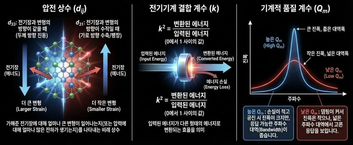
These are the parameters you read off a datasheet when choosing an element.
- Piezoelectric constant (d_ij) — how much strain you get per unit field. d33 describes the case where field and strain share a direction (thickness motion) and d31 the perpendicular case (lateral contraction and expansion). The first subscript is the electrical direction, the second the mechanical one.
- Piezoelectric voltage constant (g33) — how much voltage a given force produces. The relation is g = d ÷ (ε₀·εr), so it grows as permittivity falls. For transmitting, d matters; for receiving, g matters.
- Electromechanical coupling factor (k) — the fraction of input energy converted to the other form. k² is that fraction; the remainder is not lost but simply returned unconverted.
- Mechanical quality factor (Q_m) — the sharpness of the resonance. A high Q_m gives large amplitude at resonance but a narrow band; a low Q_m gives smaller amplitude with a flat response over a wide band. An ultrasonic transducer driving a single 40kHz tone hard is the textbook case where high Q_m wins.
Why d and g are both needed becomes obvious in numbers. PZT-4 has a large d33 of 289pC/N, but its permittivity of 1,300 holds g33 down to 25.1mV·m/N. PVDF has a d33 of only 33pC/N, one ninth as much, yet its permittivity of just 12 lifts g33 to 311mV·m/N — twelve times PZT's. That single line explains why PZT dominates as a transmitter while PVDF wins as a microphone or hydrophone.
Material families compared — the choice in numbers
Line the representative piezoelectric materials up against the same yardstick and the design choice becomes visible. The d33 and permittivity values are measured figures from the literature; g33 and k² are computed directly from the relations above.
| Material | d33 [pC/N] | Rel. permittivity εr | g33 [mV·m/N] | Coupling k (k²) | Q_m | Curie / service limit | Character |
|---|---|---|---|---|---|---|---|
| Quartz (α-quartz) | 2.3 (d11) | 4.5 | 57.7 | 0.10 (1.0%) | over 100,000 | 573℃ transition | Ultra-stable, ultra-low loss, minute output — frequency reference |
| BaTiO₃ ceramic | 190 | 1,700 | 12.6 | 0.49 (24%) | about 400 | 120℃ | First-generation ceramic, displaced by its low Curie point |
| PZT-4 (hard) | 289 | 1,300 | 25.1 | 0.70 (49%) | about 500 | 328℃ | High power, continuous drive — the ultrasonic transmit standard |
| PZT-5H (soft) | 593 | 3,400 | 19.7 | 0.75 (56%) | about 65 | 193℃ | High sensitivity and bandwidth, poor with heat — receive and medical |
| PVDF (polymer) | −33 | 12 | −311 | 0.19 (3.6%) | about 10 | around 80℃ | Thin, flexible, very broadband; too weak to transmit |
| AlN thin film | 5.15 | 10.5 | 55.4 | 0.23 (5.3%) | over 1,000 | no poling needed (non-ferroelectric) | Semiconductor-process compatible, lead-free — MEMS and PMUT |
| ZnO thin film | 12 | 10.9 | 124.3 | 0.28 (7.8%) | high | no poling needed | Better coupling than AlN, process-contamination concerns |
| KNN-based lead-free | 416 | 1,570 | 29.9 | 0.61 (37%) | low | 253℃ | Lead-free alternative; composition repeatability still an issue |
What the table teaches is not the individual values but the structure of the trade-offs. First, d33 and Q_m generally move in opposite directions. PZT-5H strains twice as far as PZT-4 but its Q_m is one eighth, so continuous drive cooks it. A directional loudspeaker is a continuous-wave, high-power application that emits 40kHz for hours, so the answer is not sensitivity but the hard family (PZT-4, PZT-8). Second, the thin-film family (AlN, ZnO) has a d33 two orders of magnitude smaller yet can be fabricated as hundreds-of-micrometre elements in enormous numbers by semiconductor processing. That is the direct route around the 4.29mm spacing constraint from Part 8. Third, lead regulation keeps KNN-based lead-free ceramics in active research, but they still do not match hard PZT's Q_m and thermal headroom.
Poling and the Curie point — piezoelectricity is made, and can be lost
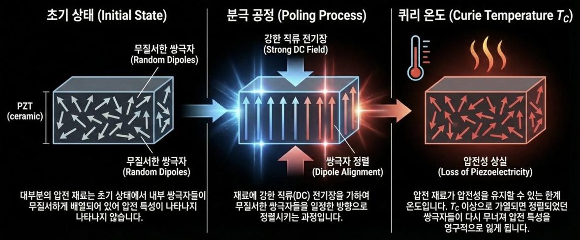
Freshly fired PZT ceramic is not piezoelectric at all: its internal dipoles are disordered. Ferroelectric domains tens of nanometres across point in every direction, so the whole cancels out. Only after poling — applying a strong DC field during manufacture to align the dipoles — does it become a piezoelectric material. In practice a field of several kV/mm is held for tens of minutes at a temperature below the Curie point, and the part is then cooled with the field still applied. Align while the domain walls move easily; remove the field only after everything has set.
There is a hard limit as well. Heat the material past its Curie temperature (T_c) and the crystal returns to a centrosymmetric phase, the alignment collapses, and the piezoelectricity is permanently gone. In real designs, though, T_c itself is not the number to watch. Depolarisation arrives by three routes, and all three erode performance long before T_c is reached.
| Depoling mechanism | How it works | Practical rule | Risk in a directional loudspeaker |
|---|---|---|---|
| Thermal | Thermal energy agitates domain walls and undoes the alignment | Keep continuous service temperature below half of T_c — about 160℃ for PZT-4 | Internal temperature rise in a densely packed array of hundreds of elements |
| Electrical | A field opposing the poling direction flips domains back | Drive below the coercive field, roughly 1kV/mm for hard PZT | Reverse voltage swing under high-power drive |
| Mechanical | Strong compression or shock forcibly reorients domains | Stay within rated compressive stress; use prestress to avoid tension | Diaphragm fatigue and cracking from overdrive |
A fourth factor, time, is quietly added to these. The domain arrangement immediately after poling is metastable, so permittivity and piezoelectric constants drift downward in proportion to the logarithm of time even when nothing is done to the part. This is ageing, and in hard PZT it amounts to a few per cent per decade of time. Hard materials age more slowly than soft ones because their domain walls are firmly pinned — saying that Q_m is high and saying that domain walls barely move are essentially the same statement. Every reason thermal management dominates high-power transducer design is gathered here.
Working as a loudspeaker — from volts to sound
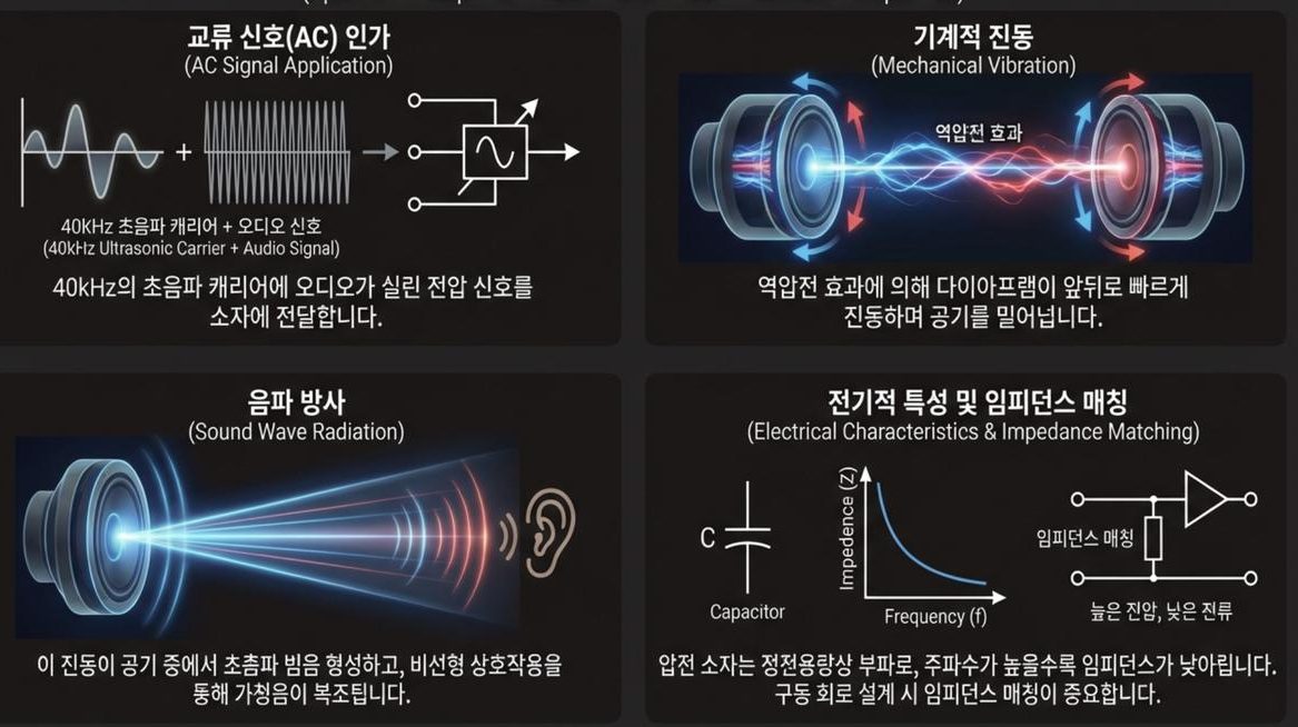
- Apply the AC signal — a voltage carrying audio on a 40kHz ultrasonic carrier is applied to the element.
- Mechanical vibration — the converse effect drives the diaphragm back and forth forty thousand times a second, pushing air.
- Acoustic radiation — that vibration forms the ultrasonic beam, and the nonlinear interaction of Part 6 demodulates the audible sound.
- Impedance matching — electrically the element is a capacitive load, so its impedance falls as frequency rises. That is why matching matters in the drive circuit.
How far must it move — the real size of the displacement
Let us put numbers on step two. In a plane wave the sound pressure p and the particle velocity u are linked by the characteristic impedance of the medium — the 413 Rayl of air we met in Part 4. For sinusoidal motion the displacement amplitude ξ follows:
p = ρc·u , u = 2πf·ξ → ξ = p ÷ (2πf·ρc)
Substituting 40kHz and air (ρc = 413 Rayl) gives the table below; sound pressure is converted to dB against the 20μPa reference.
| Surface SPL | Pressure p [Pa] | Particle velocity u [mm/s] | Required displacement ξ |
|---|---|---|---|
| 100dB | 2.00 | 4.84 | 19.3nm |
| 110dB | 6.32 | 15.3 | 60.9nm |
| 120dB | 20.0 | 48.4 | 193nm |
| 130dB | 63.2 | 153 | 609nm |
In Part 7 the carrier level assumed for a practical parametric loudspeaker was 130dB. Producing it requires the diaphragm to move 0.6μm — a hundredth of the thickness of a human hair. That sounds trivial, and it is where the trouble starts. Using PZT-4 directly, with d33 = 289pm/V, the voltage needed for 609nm is
V = 609nm ÷ 289pm/V ≈ 2,110V
You cannot put 2kV across a palm-sized loudspeaker. This is where resonance rescues the design. Driving at the resonant frequency multiplies the displacement by roughly Q_m, so with hard PZT at Q_m = 500 the requirement drops to 4.2V. Even at Q_m = 100, 21V suffices. This is why piezoelectric transducers are, without exception, resonant devices — not a choice but a necessity. And the moment you use resonance, you lose bandwidth. Every design problem in Part 10 descends from that single trade.
What the circuit sees — a capacitive load
From the driver's point of view, a piezoelectric element is not a resistor but a capacitor. Away from resonance essentially only the clamped capacitance C₀ is visible, so the impedance is |Z| = 1 ÷ (2πf·C₀). Evaluated at 40kHz:
| Clamped capacitance C₀ | Impedance at 40kHz | Tuning inductor for resonance | Reactive current at 20V rms |
|---|---|---|---|
| 1nF | 3,979Ω | 15.8mH | 5.0mA |
| 2nF | 1,989Ω | 7.92mH | 10.1mA |
| 5nF | 796Ω | 3.17mH | 25.1mA |
| 10nF | 398Ω | 1.58mH | 50.3mA |
| 20nF | 199Ω | 0.79mH | 101mA |
The implication for array design is substantial. If one element is 2nF, then paralleling 400 of them gives 0.8μF and the impedance at 40kHz falls below 5Ω. The reactive current — current that makes no sound and merely charges and discharges the capacitance — reaches several amperes. Real drive stages therefore split the array into channels of a few elements each and add a series or parallel inductor to cancel the capacitance. The third column of the table is that value: for a 2nF group, 7.9mH makes the reactances cancel at 40kHz and the circuit look resistive. Part 8 required each channel to carry its own phase for steering; each of those channels also carries a resonant matching network like this one.
Limits and common misconceptions
- "Piezoelectric elements consume a lot of power." They are voltage-driven devices. The real power radiated as sound is small; what strains the circuit is the reactive current in the table above. Current capability and slew rate, not wattage, size the drive stage.
- "A bigger d33 makes a better loudspeaker." Under continuous high power, Q_m and dielectric loss dominate over d33. A soft material with twice the d33 routinely fails from self-heating first.
- Piezoelectric elements are not linear. The datasheet d33 is a small-signal value measured at low field. Raise the drive field and domain-wall motion joins in, increasing the effective d33 while adding hysteresis and harmonic distortion. In a parametric loudspeaker that distortion is indistinguishable from the nonlinearity of the air itself and simply shows up as degraded audio.
- "It is safe right up to the Curie point." The practical ceiling is near half of T_c, and there is a feedback loop in which loss-generated heat increases loss further, so inadequate cooling can drive local spots to T_c.
- A single element will never be a directional loudspeaker. As the wavelength-to-aperture ratio in Part 1 and the element-count-versus-beamwidth table in Part 8 showed, a narrow beam comes from aperture. The piezoelectric effect handles conversion only; directivity is made by the geometry of the array.
Summary
A piezoelectric ceramic converts between force and electricity in both directions, and a loudspeaker uses the converse half. Performance is read from four numbers — d, g, k and Q — and piezoelectricity is created by poling and slowly erased by heat, field, stress and time. Restated as this article's numbers: a 130dB carrier needs 609nm of motion; producing it off resonance would take 2,110V; on resonance at Q_m = 500 it takes 4.2V; a 2nF element presents 1,989Ω at 40kHz; and continuous high power calls for hard PZT. Those are the coordinates of element design. Next time we turn this element into a real product — resonant structures and array layout in transducer design.
Series guide
"The Science of Directional Loudspeakers" runs in the following order.
- What is a directional loudspeaker — a flashlight for sound
- Carrying sound on sound you cannot hear — first steps in operating principle
- Applications — exhibitions, safety, retail, offices
- What is ultrasound — definitions, types, propagation
- Why ultrasound — generation principles and application map
- The magic of air becoming a loudspeaker — PAA nonlinear acoustics
- PAA theory in depth — Berktay, Westervelt, KZK
- Aiming sound — phased arrays and beamforming
- The piezoelectric effect — the moment electricity becomes sound (this article)
- Coming next: transducer design, Nyquist, modulation, signal processing
This series is a blog adaptation of self-produced lecture material researched and compiled on ultrasonic directional audio technology. The figures are excerpted from that material.
References
- B. Jaffe, R. S. Roth & S. Marzullo, "Piezoelectric Properties of Lead Zirconate-Lead Titanate Solid-Solution Ceramics," J. Appl. Phys. 25(6), 809 (1954) : the original report of the PZT solid solution and its morphotropic phase boundary — the starting point for today's transducer materials
- D. A. Berlincourt, B. Jaffe & others, "Piezoelectric Properties of Polycrystalline Lead Titanate Zirconate Compositions," Proc. IRE 48(2), 220 (1960) : systematic d, k, Q and permittivity data by composition — the lineage of the PZT-4 and PZT-5H figures used here
- R. Bechmann, "Elastic, Piezoelectric, and Dielectric Constants of Polarized Barium Titanate Ceramics," JASA 28(3), 347 (1956) : measured constants for the first-generation BaTiO₃ ceramic — the basis of the BaTiO₃ row
- H. Kawai, "The Piezoelectricity of Poly(vinylidene Fluoride)," Jpn. J. Appl. Phys. 8(7), 975 (1969) : the paper showing a polymer can be piezoelectric — source of PVDF's low permittivity and high g33
- M.-A. Dubois & P. Muralt, "Properties of aluminum nitride thin films for piezoelectric transducers and microwave filter applications," Appl. Phys. Lett. 74(20), 3032 (1999) : measured piezoelectric constants of sputtered AlN films — the basis of the AlN row
- P. Muralt, "Piezoelectric aluminum nitride thin films for microelectromechanical systems," MRS Bulletin 37(11), 1051 (2012) : properties and MEMS use of non-ferroelectric piezoelectric films that need no poling
- Y. Saito et al., "Lead-free piezoceramics," Nature 432, 84 (2004) : textured KNN-based lead-free ceramics reaching PZT-class d33 — the basis of the lead-free row
- IEEE Std 176-1987, IEEE Standard on Piezoelectricity : the international definitions of the piezoelectric equations and subscript conventions (d33, d31, k, Q_m)
- T. E. Gómez Álvarez-Arenas, "Acoustic impedance matching of piezoelectric transducers to the air," IEEE TUFFC 51(5), 624 (2004) : the enormous impedance gap between piezoceramic and air, and matching layers — the problem carried into Part 10
- M. Yoneyama et al., "The audio spotlight: An application of nonlinear interaction of sound waves to a new type of loudspeaker design," JASA 73(5), 1532 (1983) : the first airborne parametric loudspeaker, built from piezoelectric ultrasonic elements on a plane
- J. Li et al., "Piezoelectric micromachined ultrasonic transducer array for micro audio directional speaker," IEEE ICMA 2013, 450 : thin-film piezoelectrics arrayed by semiconductor processing — the PMUT route around element-size limits
- Piezoelectricity — Wikipedia : overview of the symmetry classification (20 piezoelectric and 10 polar groups out of 32) and the Curie brothers' 1880 discovery