When folding smartphones first appeared, many people asked the same question. "How can a screen fold? Isn't it glass?" The answer is simple — the substrate of a folding screen is not glass but a plastic film. Yet, curiously, the factory that makes that film still begins its work on a sheet of glass. This first article of the PI chapter starts from that paradox and covers the material (why polyimide), the structure (why two layers), and the chemistry by which a liquid becomes a film. The actual coating, drying and curing processes and their equipment are the subject of the next article (Part 3).
Glass is not the substrate — it is a carrier
Every tool in a display fab — coaters, steppers, deposition chambers — is designed to move and hold a rigid, flat plate. A floppy film about 10㎛ thick, roughly a tenth of a sheet of paper, cannot travel between these tools on its own. So the industry settled on a strategy: "build the film on glass, then peel it off when everything is done."
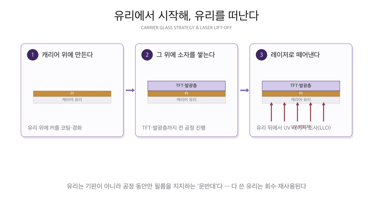
Coat liquid polyimide onto a glass plate and cure it, and you get a thin film substrate bonded tightly to the glass. Transistors and the emitting layers are all built on top of it, and at the very end an ultraviolet laser is fired through the back of the glass to release the film alone — this is LLO (Laser Lift-Off). The laser passes through the glass and momentarily decomposes only the PI/glass interface, so the finished panel comes away with its film, and the spent carrier glass is collected and reused. The glass plays the part of "substrate" from beginning to end, but in truth it is a carrier that merely holds the film during processing.
Why take such a detour? The surface strain of a plate under bending is roughly as follows, in terms of thickness t and bending radius R.
surface strain ε ≈ thickness t ÷ (2 × bending radius R)
Assume a fold radius of 3mm. A 0.5mm glass sheet then sees a surface strain of 8.3% — glass already fractures near 0.2%, so the number is meaningless. Thin that same glass to 30㎛ and it drops to 0.50%, still above the fracture strain of an inorganic material. A 10㎛ polyimide film, by contrast, sees 0.167%, and being a polymer it absorbs that much elastically. In other words, most of what we call "foldability" comes not from the material but from thickness — and the carrier glass resolves the contradiction "rigid while being made, thin once it is made" by separating the two in time.
Why polyimide, of all things
The requirements for a substrate plastic are brutal. It must survive hundreds of degrees several times in later processes, stay stable against a range of solvents, acids and bases, and not crack after hundreds of thousands of folds. Common plastics such as PET begin to deform somewhere around 100~200℃ and are eliminated at once.
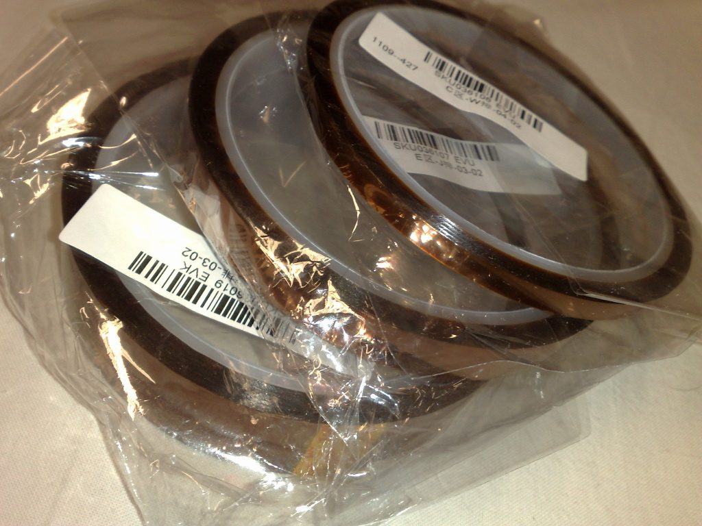
- Polyimide film tape used in electronics work. The distinctive amber colour is its signature.
- It does not burn even under a soldering iron, so it is commonly used to protect boards.
- PI for display substrates is essentially an ultra-pure, ultra-flat version of this film.
- Photo: Wikimedia Commons (Dsimic, CC BY-SA 3.0)
Line the candidate materials up by glass transition temperature and it becomes obvious how narrow the choice is. PI's own cure (Part 3), dehydrogenation (Part 4) and crystallisation (Part 6) alone bring the substrate above 400℃ several times.
| Material | Glass transition (Tg) | Thermal expansion | Fit as a backplane substrate |
|---|---|---|---|
| PET (polyethylene terephthalate) | 67~81℃ | — | No — cannot even survive drying |
| PC (polycarbonate) | 147℃ | 65~70 ppm/K | No — for optical parts |
| Display-grade PI | 390℃ or higher | 10~40 ppm/K | Yes — effectively the only choice |
| Alkali-free glass (reference) | strain point in the 600℃ range | about 3.2 ppm/K | Suitable but does not fold |
The PET and PC figures come from published material data (PET · PC); the PI figures are the ranges a patent on polyimide film for flexible display substrates specifies directly in its claims (US 11,472,922 B2). The 3.2 ppm/K for glass is the same value used in the thermal stress calculation of Part 5.
The one polymer that effectively meets all of these conditions is polyimide (PI). Polyimide has worked in "the hottest places" since it was commercialised in the 1960s, and the root of its heat resistance is molecular — aromatic rings and imide rings alternate along the chain, making it stiff and expensive to break. For the same reason polyimide cannot be melt-processed: it decomposes before it melts. That property is exactly why, as we shall see, the process has no choice but to start from a liquid.
There is an extreme example. The sunshield of a large infrared space telescope is made of five layers of aluminium-coated polyimide film. With one face below minus 200℃ and the other facing the Sun directly, polyimide was chosen as the material that protects the telescope (official sunshield description).

A polyimide membrane sample for a sunshield. Photo: Wikimedia Commons (CC BY 2.0)
The spec sheet for substrate PI, read as numbers
You cannot buy a material on the strength of "good heat resistance" alone. Below are the values the patent cited above states directly in its specification and claims.
| Item | Specified range | Why this value |
|---|---|---|
| Glass transition temperature | 390℃ or higher | Must survive a 400℃ cure and later anneals |
| Thermal expansion (100~350℃) | 10~40 ppm/K, 22 or less preferred | To reduce stress against the glass carrier |
| Modulus | 3~8 GPa | Must not stretch during handling despite being thin |
| Film thickness | 5~10㎛ | Compromise between bending strain and handling |
| Out-of-plane retardation | 200~600 nm | To prevent colour shift under the polariser |
| Varnish solid content | 15~20 wt% | Trade-off between coatable viscosity and thickness |
| Cure condition | 5℃/min ramp, 80℃ for 30 min → 400℃ for 30 min | Separates solvent removal from imidisation |
Here the demand to lower thermal expansion and the demand to control retardation pull against each other. Lowering thermal expansion means straightening the chains and aligning them in the plane, and an aligned film is birefringent (Polymer 321, 128085 (2025)).
You do not buy a finished film — the varnish
PI for display substrates is not a finished film bought and laminated on. A liquid precursor called a varnish is applied directly onto the glass and turned into a film in place. Starting from a liquid is the only way to get a particle-free, ultra-flat surface — to stack nanometre-thick transistors on it, the surface roughness itself must be managed at the nanometre scale — and above all, polyimide does not melt.
The varnish is a solution of polyamic acid (PAA), the precursor of polyimide, dissolved in an organic solvent. The representative solvent is NMP (N-methyl-2-pyrrolidone); polyimide coatings are usually applied as a polyamic acid solution in an aprotic solvent of this kind. The solid content is the minority and the solvent the majority — the patent specifies 15~20 wt% solids (more preferably 15~18%) and describes an example in which a 15% varnish is applied by slit coating to form a wet film (US 11,472,922).
That number translates immediately into a process condition. Ignoring density differences, obtaining a 10㎛ dry film from a 15% varnish requires a wet film of 66.7㎛ (10 ÷ 0.15). At 18% solids it is 55.6㎛; at 20%, 50.0㎛. The figure quoted in the next article — "coat about 70㎛ and leave 10㎛" — is the result of that division.
So roughly eight tenths of what is applied is solvent that will later leave. Raising the solid content to thin the wet film sounds convenient, but viscosity climbs steeply with solids and the liquid becomes hard to push uniformly through a slit nozzle. That is why the patent caps solids at 20%.
The chemistry that turns liquid into film — imidisation
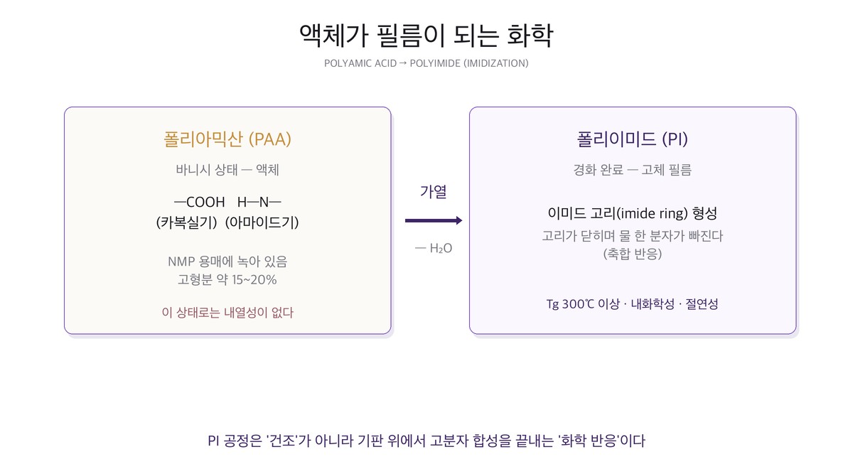
Polyamic acid is already a polymer. Bring a dianhydride carrying two anhydride groups together with a diamine carrying two amine groups in a solvent, and even at room temperature the two monomers link alternately into a long chain. Carboxyl and amide groups hang from that chain in pairs — an "unfinished polyimide", soluble in solvent, whose rings have not yet closed. Apply heat and two things happen in order.
- Solvent evaporation — the solvent that made up eight tenths of the solution leaves and only solids remain. NMP is a high-boiling solvent at about 202℃ (N-Methyl-2-pyrrolidone), so it does not dry easily at room temperature and only escapes once the temperature is raised substantially.
- Imidisation — a condensation in which the carboxyl and amide groups close a ring while releasing one molecule of water. Only when this ring is complete does the material become "polyimide", with its characteristic heat resistance and amber colour.
Here too the arithmetic is instructive. Take the classic PMDA-ODA system: the polyamic acid repeat unit has a molecular weight of 418.36, and imidisation expels two water molecules (36.03) per repeat unit — meaning 8.61% of the solid mass evaporates as water. Quite apart from the solvent, water is generated a second time inside a film that already looks solid, and has to leave.
This "water that appears later" is what makes the process difficult. If the surface densifies first and water forms underneath, it has no escape route and becomes a bubble or a microcrack. So the cure profile deliberately separates the solvent-removal window from the ring-closing window by temperature — the patent's "80℃ for 30 min → 400℃ for 30 min" is the simplest form of that separation.
The extent of imidisation is checked by infrared spectroscopy (FTIR): the degree of imidisation is calculated from the growth of the absorption peak unique to the imide ring against the decline of the amic acid peak. Even with the same monomers, different linkage isomers close their rings at different rates and require different temperatures (Polymer Journal 22, 725 (1990)), so a change of formulation means the temperature profile must be reworked as well. In the end the PI step is not drying but a chemical process that completes a polymer synthesis on the substrate.
Glass and film pulling apart — thermal expansion mismatch
Now we can calculate why the 10~40 ppm/K in the spec table matters. PI cured at 400℃ cools to room temperature while bonded to the glass. The PI wants to shrink a great deal and the glass barely at all; because they are bonded, neither can shrink freely, and that suppressed contraction becomes tensile stress inside the film. Extending the thermal stress equation of Part 5 to a two-material case gives the following.
film stress σ ≈ [ E / (1 − ν) ] × (α_film − α_glass) × ΔT
PI modulus is 3~8 GPa from the table, so the midpoint 5 GPa was used, with a typical polymer Poisson's ratio of 0.34, glass at 3.2 ppm/K, and a temperature drop from 400℃ to 25℃, i.e. 375K.
| PI thermal expansion | Difference vs glass | Stress (E=5GPa) | Range for E=3~8GPa | Bow radius of 0.5mm glass |
|---|---|---|---|---|
| 10 ppm/K | 6.8 ppm/K | about 19.3 MPa | 11.6~30.9 MPa | — |
| 20 ppm/K | 16.8 ppm/K | about 47.7 MPa | 28.6~76.4 MPa | about 8.3 m |
| 30 ppm/K | 26.8 ppm/K | about 76.1 MPa | 45.7~121.8 MPa | — |
| 40 ppm/K | 36.8 ppm/K | about 104.5 MPa | 62.7~167.3 MPa | about 3.8 m |
The last column is the bow radius of the carrier glass from the Stoney equation — how concave a 0.5mm glass sheet becomes under the tensile stress of a 10㎛ PI film on it. With a 40 ppm/K PI the radius of curvature falls to 3.8m, and on a glass sheet more than 2m on a side that degree of bow directly affects robot chucking and exposure focus.
This is why the patent tightens the limit in stages — "40 ppm/K or less, preferably 22 or less". Stress is linear in the expansion difference, so halving 40 to 20 more than halves the stress (104.5 → 47.7 MPa) (J. Applied Polymer Science 34, 815 (1987)). There is a price, however. The stiffer the chain, the less the film stretches and the more brittle it becomes, so it fails to absorb strain when folded and cracks. Real formulations therefore mix rigid backbones with flexible linkages to find a middle value.
Not one layer but a sandwich — the stack
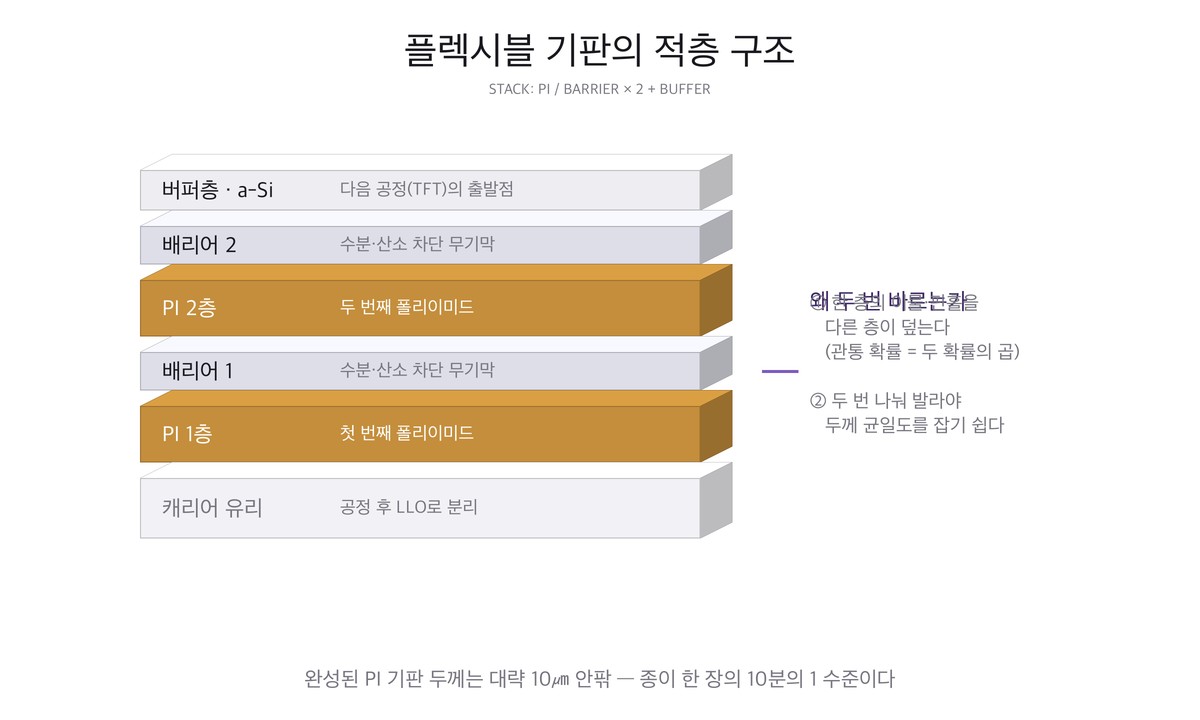
- A real flexible substrate is not a single PI layer but a sandwich of PI → barrier → PI → barrier → buffer.
- The barrier is an inorganic thin film (silicon oxide or nitride family) that blocks moisture and oxygen.
- Once the top buffer layer is in place, the substrate is ready for the next step (silicon deposition).
- The two PI layers together are controlled to about 10㎛.
Why stack them like this? There are three reasons.
First, OLED is extremely vulnerable to moisture. Organic emitters meet a trace of moisture or oxygen and the pixel dies as a black spot. Glass is a perfect barrier in itself, but PI, being a plastic, lets moisture through slowly. So a dense inorganic film is laid over the PI to cut the path (Flexible OLED).
Second, it is a probability game against defects. Any single layer will have some particles or pinholes. Stack two sets and a defect can only penetrate if the defects of both layers land in exactly the same place; that probability is the product of the two and collapses — one in ten thousand per layer becomes one in a hundred million for both.
Third, splitting the thickness makes uniformity easier. Making 10㎛ in one pass demands a 66.7㎛ wet film, but split in two it is only 33.3㎛ each time. The thicker the wet film, the larger the solvent concentration gradient between surface and bottom during drying, so simply halving it greatly reduces the risk of mottle.
The barrier and buffer do more than block moisture. The silicon film above them sees anneals over 400℃, and if PI touched the silicon directly, residues from the PI could contaminate it. The inorganic barrier doubles as a diffusion blocking layer between them (J. Display Technology 11, 666 (2015)).
The last gate — peeling with a laser
When processing is finished the film has to come off the glass. Pulling it mechanically tears the film or leaves stress in the devices, so an ultraviolet laser is fired through the back of the glass to decompose only the interface. Two conditions must hold — the glass must transmit that wavelength, and the PI must absorb all of it at its surface. Both are satisfied simultaneously in the ultraviolet. Polyimide, rich in aromatic rings, absorbs UV strongly with a penetration depth of only a few hundred nanometres, so the energy concentrates at the interface and the transistors and emitting layers above receive almost no heat.
Reported LLO conditions cluster broadly in the 100~250 mJ/cm² band — about 110 mJ/cm² has been reported for wrinkle-free release of an ultrathin PI film (Applied Surface Science 499, 143910 (2020)), and about 240 mJ/cm² as the threshold for single-shot, non-overlapping separation (Science China Technological Sciences 62, 233 (2018)). The values differ because PI composition, thickness, beam intensity distribution and overlap ratio all differ.
The designer has several handles — flattening the beam cross-section (top-hat) so that every location receives the same energy (Optics & Laser Technology 142, 107245 (2021)), inserting a sacrificial layer between glass and PI so that only that layer decomposes (Vacuum 170, 108968 (2019)), or using a broadband flash instead of a laser (Polymers 13, 546 (2021)) have all been tried. Decomposition residue remains on the back of the PI after release, so a backside clean and protective film lamination follow immediately after LLO.
Three common misconceptions
- "Folding screens use no glass" — the substrate is indeed PI, but it sits on glass while being made, and a cover window of thin glass or colourless transparent polymer goes back on top of the finished screen. Glass did not disappear; its role changed (Micromachines 12, 233 (2021)).
- "It folds because PI is flexible" — only half true. As the strain calculation showed, the same material will not fold if it is thick. The main source of flexibility is thickness; the material's job is to survive repeated deformation at that small thickness.
- "You buy PI film and stick it down" — a finished film cannot meet the surface roughness and dimensional stability that transistor processing demands. What appears on the purchase specification is not a film but the viscosity and solid content of a varnish.
Summary — and the next article
- A flexible substrate is a polyimide film that starts as a liquid and is made in place on a glass carrier.
- The varnish is polyamic acid + NMP at 15~20% solids — a 10㎛ dry film needs a 50~67㎛ wet film.
- Heating is not drying but imidisation, which expels two additional water molecules per repeat unit (8.6% of the mass).
- The specification reads Tg 390℃ or higher · expansion 10~40 ppm/K · modulus 3~8 GPa · thickness 5~10㎛. At 40 ppm/K the mismatch against glass produces stress on the order of 100 MPa.
- The substrate is a PI/barrier sandwich, and the final LLO decomposes only the interface at 100~250 mJ/cm².
The next article (PI ②) moves into the process and equipment that actually apply and cure this liquid on glass — how a slit coater sweeps a large glass sheet, why drying under vacuum is done in two stages, the staircase of oven temperatures (about 120℃ → 350℃ → 450℃), and why four kinds of pump that push the solution give four different answers.
References
- US 11,472,922 B2 — Polyimide film, flexible substrate using same, and flexible display comprising flexible substrate : source of the specification table in this article
- EP 2186848 A1 — Process for production of polyimide film, and polyamic acid solution composition : solution composition and degassing under reduced pressure
- "Reactivity of Poly(amic acid) Isomers in Thermal Imidization," Polymer Journal 22, 725 (1990) : ring-closure rate by isomer
- "Residual stress and thermal expansion of spun-on polyimide films," J. Applied Polymer Science 34, 815 (1987) : measured thermal expansion and residual stress of PI films
- "LTPS TFT Process on Polyimide Substrate for Flexible AMOLED," J. Display Technology 11, 666 (2015) : LTPS processing on a PI substrate
- "Laser lift-off systems for flexible-display production," J. Information Display 15, 1 (2014) : requirements for LLO equipment
- "Theoretical and experimental studies of laser lift-off of nonwrinkled ultrathin polyimide film," Applied Surface Science 499, 143910 (2020) (about 110 mJ/cm²) · "Experimental study of laser lift-off of ultra-thin polyimide film for flexible electronics," Science China Technological Sciences 62, 233 (2018) (about 240 mJ/cm²) : basis for the fluence range quoted
- "Laser lift-off of polyimide thin-film from glass carrier using DPSS laser pulses of top-hat square beam profile," Optics & Laser Technology 142, 107245 (2021) · "Sacrificial layer for laser lift-off process for flexible-display production," Vacuum 170, 108968 (2019) : flat beam profile and sacrificial layer
- "Investigation of the Chemical Structure of Ultra-Thin Polyimide Substrate for the Xenon Flash Lamp Lift-off Technology," Polymers 13, 546 (2021) · "Ultra-high Tg colorless polyimide film…," Polymer 321, 128085 (2025) · "Transparent and Flexible SiOC Films on Colorless Polyimide Substrate…," Micromachines 12, 233 (2021) : flash-based release and colourless PI
- Polyimide · N-Methyl-2-pyrrolidone · PET · Polycarbonate · Flexible OLED — Wikipedia : material values in the comparison table and the boiling point of NMP (about 202℃)
- Sunshield — official description : five-layer polyimide membrane sunshield
- Photos: polyimide tape — Wikimedia Commons (Dsimic, CC BY-SA 3.0) · sunshield membrane — Wikimedia Commons (CC BY 2.0)