In the previous article we looked at the material — a polyamic acid solution at 15~20% solids, and the chemistry by which imidisation turns it into a film. This article covers the process and equipment that actually turn that liquid into a film on glass. There are only three actions — coat, dry, bake. Yet with cleaning and inspection interleaved between them, a single substrate spends a day and a half to two days in this section.
The whole flow — the same cycle, twice
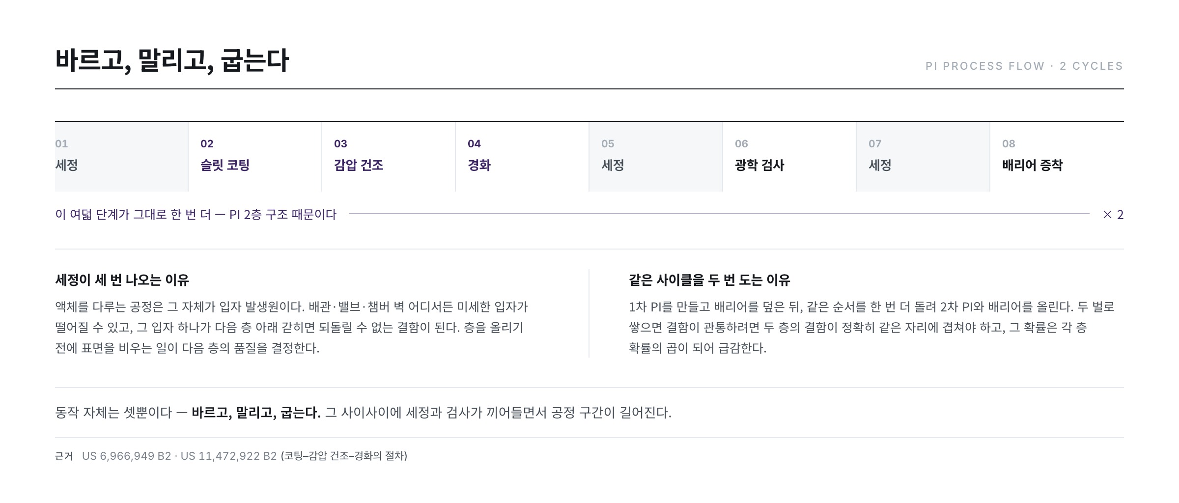
Two things stand out when the process map is unfolded. First, cleaning appears three times. Second, the whole cycle runs twice — because of the two-layer PI structure seen in the previous article. The first PI is made and covered with a barrier, the same sequence runs once more for the second PI and barrier, and only after the buffer layer is stacked does the substrate move on.
The reason for so much cleaning is simple. Any process that handles liquid is itself a particle source. Fine particles can shed from piping, valves or chamber walls anywhere, and a single particle trapped beneath the next layer becomes a defect that can never be repaired. Emptying the surface before adding a layer determines the quality of that layer.
① Coating — slit coating
Spreading a liquid film tens of micrometres thick uniformly over large-area glass is harder than it sounds. Spin coating, which spreads liquid by rotation, works for round wafers but cannot be used for square glass more than a metre on a side. Hence slit (slot-die) coating — the solution is pushed at a fixed flow rate through the narrow gap of a nozzle as long as the glass is wide, while the nozzle sweeps across the glass.
| Method | Spreading force | Large square substrate | Material loss | Main defects |
|---|---|---|---|---|
| Spin coating | Centrifugal force | Unsuitable (corner sag, spin-off) | Very large | Streaks, edge bead |
| Slit (slot-die) coating | Pump pressure + travel | Suitable — current standard | Small (applied = required) | Cross-direction stripes, ribbing |
| Roll coating | Nip between rolls | Possible but contact-based | Moderate | Roll marks, contact contamination |
| Spray coating | Atomised droplets | Possible (tolerant of topography) | Large (overspray) | Droplet marks, thickness scatter |
The decisive reason slit coating became the standard is that what is applied is what is needed. Spin coating flings most of the poured liquid away; in slit coating the volume the pump delivers becomes the film. With an expensive varnish, that difference is cost.
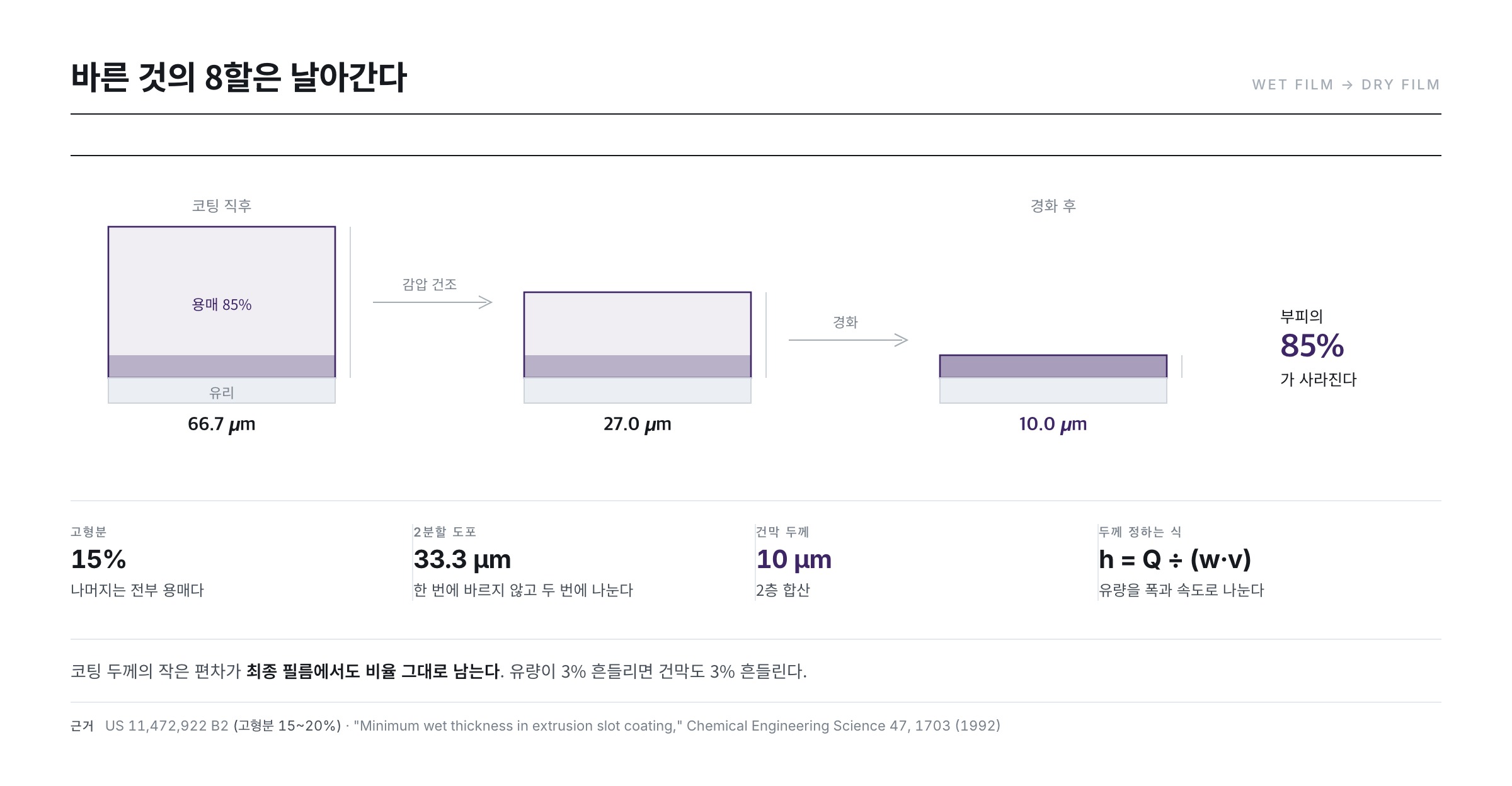
Here the "15~20% solids" of the previous article returns as a number. The wet film is applied at about 70㎛ (and even that is split into two passes), but once the solvent has left, the remaining film is about 10㎛ for the two layers combined. Roughly eight tenths of the volume disappears. A small deviation in coated thickness therefore survives in the final film in exactly the same proportion — the uniformity target is managed at the level of a few percent.
Thickness is decided by a division
The wet thickness in slit coating is set by a surprisingly simple expression: the volumetric flow rate divided by the coating width and the travel speed.
wet thickness h = flow rate Q ÷ (coating width w × travel speed v)
Take a Gen-8 class glass sheet (about 2.2m × 2.5m, area 5.5㎡) and a single pass of 33.3㎛ wet film (corresponding to a 5㎛ dry layer, since coating is split in two). Substituting real numbers gives the following.
| Travel speed | Required flow rate | Time for a 2.5m pass | Volume applied |
|---|---|---|---|
| 50 mm/s | 3.66 mL/s (about 220 mL/min) | 50.0 s | 183 mL |
| 100 mm/s | 7.33 mL/s (about 440 mL/min) | 25.0 s | 183 mL |
| 150 mm/s | 10.99 mL/s (about 660 mL/min) | 16.7 s | 183 mL |
The volume applied stays at 183 mL regardless of speed. Two passes make 366 mL — about a third of a milk carton poured onto one sheet of glass. Of that, the solids that survive amount to only about 39g for a single 5㎛ dry layer (assuming a PI density of 1.4 g/㎤). Everything else is solvent that later steps must evaporate and recover.
The more important lesson of this expression is that thickness is directly proportional to flow rate. A 3% wobble in flow gives a 3% wobble in dry thickness — ±0.3㎛ against a 10㎛ target. The same holds for speed, so any speed variation in the acceleration zone of the travel axis prints a thickness band right there. That is why coating equipment specifications lead with "flow stability" and "travel speed deviation".
Flow and speed cannot be combined freely, of course. The liquid bridge suspended between nozzle and substrate — the coating bead — is only stable over a limited range of combinations. If flow is too low or speed too high the bead breaks, and below that boundary no adjustment will produce a continuous film. This low-flow limit and the associated minimum wet thickness are long-standing subjects in slot-die coating research ("Minimum wet thickness in extrusion slot coating," Chemical Engineering Science 47, 1703 (1992) · "Low-flow limit in slot coating: Theory and experiments," AIChE Journal 46, 1907 (2000)). Outside the stable window, defects such as ribbing and periodic banding appear, and a review of operating limits maps that territory ("A review of the operating limits in slot die coating processes," AIChE Journal 62, 2508 (2016)).
The weak point is the pump
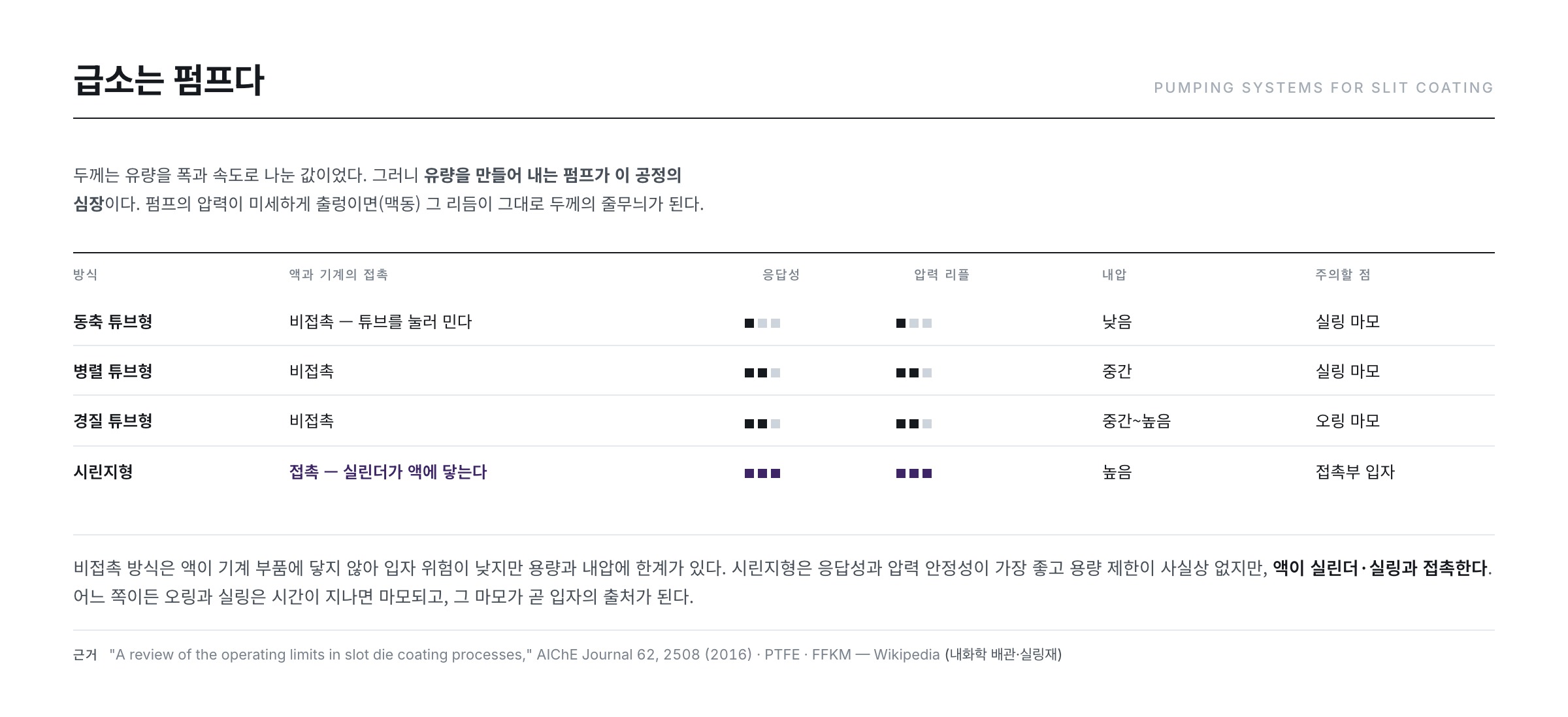
- The applied amount is set by flow rate × travel speed. The pump that creates the flow is therefore the heart of this process.
- If pump pressure oscillates slightly (pulsation), that rhythm becomes a thickness stripe.
- The division above is why — a periodic variation in flow maps one-to-one onto a periodic variation in thickness.
- With high-viscosity solutions, bubbles trapped in the flow path can also become defects (ACS Applied Materials & Interfaces 16, 11890 (2024)).
Each pump type therefore has its own character. Non-contact designs that squeeze a tube (coaxial, parallel and rigid tube types) keep the liquid away from mechanical parts and carry a low particle risk, but are limited in capacity and pressure. A syringe type has the best response and pressure stability with practically no capacity limit, but the liquid touches cylinder and seals, so particle control is demanding. Whichever is chosen, wear of O-rings and seals remains a routine inspection item.
Another handle for stabilising the bead is applying a slight vacuum behind it. A small negative pressure upstream of the nozzle pulls the liquid bridge back, widening the stable window and allowing a thinner film at higher speed for the same flow ("The Effect of Bead Vacuum on Slot Die Coating," International Polymer Processing 24, 157 (2009)). Coating is not "squeezing liquid out" but balancing pressures.
Everything that touches the liquid is under control
The supply line runs bulk supply → stirring and degassing (vacuum tank) → multi-stage filters → pump → nozzle. The degassing step in the middle matters especially, because a bubble in the solution coated as it is becomes a hole in the film. Degassing a polyamic acid solution under reduced pressure before application is described in patent examples (EP 2186848 A1).
Piping and valve materials are control items too. If they swell or leach in a strong organic solvent such as NMP they become contamination sources themselves, so wetted parts use fluoropolymer piping (PTFE and relatives) and perfluoroelastomer (FFKM) seals (FFKM). Both wrap the chain in carbon-fluorine bonds and are almost chemically inert; for semiconductor and display use, low-outgassing, low-extractable grades are specified on top of that. The chamber interior is also held at positive pressure so that outside contamination is not drawn in, and rubbing areas such as door surroundings are tracked separately as particle generation points.
② Drying — reduced pressure in two stages
The wet film just after coating is mostly solvent. Put it straight into a hot oven and the surface hardens first into a skin, and the solvent trapped underneath later boils up and pierces it — a shortcut to mottle and bubbles. So a vacuum chamber dry (VCD) step comes before the oven.
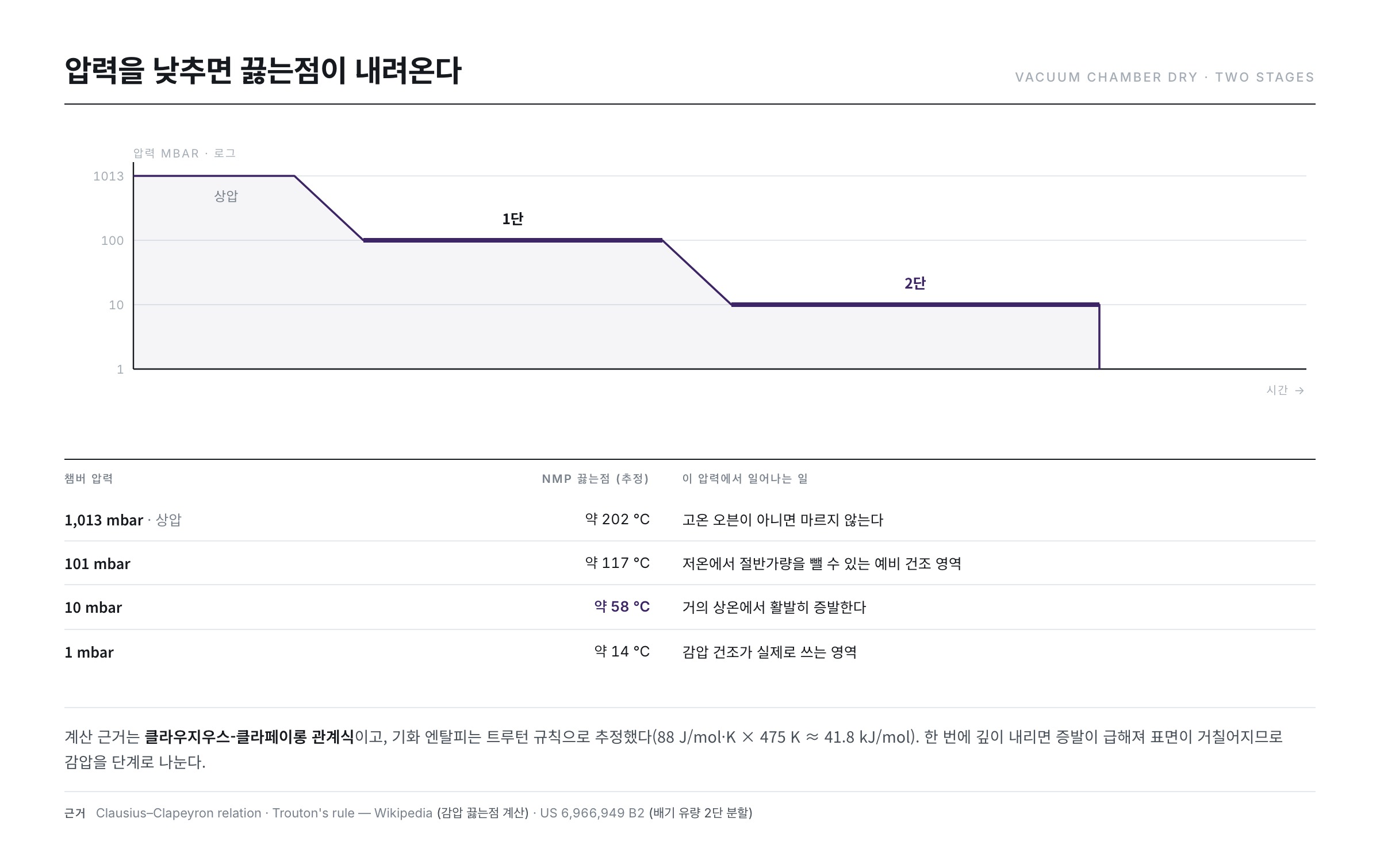
The principle is that boiling point falls with pressure. As seen in the previous article the atmospheric boiling point of NMP is about 202℃, but under reduced pressure it boils at a far lower temperature. How much lower? Substituting into the Clausius–Clapeyron relation a vaporisation enthalpy estimated by Trouton's rule (88 J/mol·K × 475K ≈ 41.8 kJ/mol) gives roughly the following (Clausius–Clapeyron · Trouton's rule).
| Chamber pressure | NMP boiling point (estimated) | Meaning for the process |
|---|---|---|
| 1,013 mbar (atmospheric) | about 202℃ | Will not dry without a hot oven |
| 101 mbar | about 117℃ | Low-temperature pre-dry region |
| 10 mbar | about 58℃ | Vigorous evaporation near room temperature |
| 1 mbar | about 14℃ | Excessively violent — surface roughening |
The last row explains why reduced-pressure drying is split into two stages. Dropping straight to 1 mbar makes the wet film evaporate as if boiling even at room temperature, roughening the surface and leaving mottle. In practice, a little over half of the solvent is removed first at shallow vacuum and low temperature, then a somewhat deeper vacuum takes the cumulative removal to about 70%. Each stage takes a few minutes. A patent on reduced-pressure drying equipment states exactly this logic — varying the exhaust flow rate in at least two steps to correct the peripheral shape of the film while keeping thickness uniform (US 6,966,949 B2).
Other patents address the same point — optimising the evaporation rate for the liquid in question and keeping the solvent vapour pressure distribution even across the coated surface (US 8,203,689 B2), and the observation that bubbles forming near the exhaust port make the solution swell locally, giving non-uniform thickness that leads to display defects (US 7,437,832 B2). What matters is not only "how far the pressure is lowered" but "how equally it is lowered across the whole substrate".
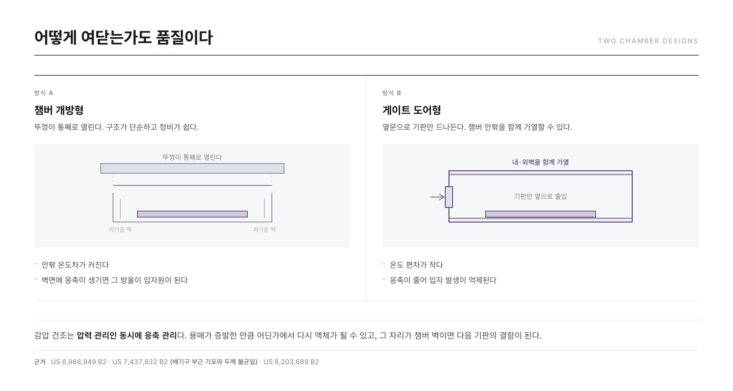
- How the chamber opens and closes is a quality issue too.
- The open type lifts the whole lid, so the inside/outside temperature difference grows, and condensation on the walls turns those droplets into a particle source.
- The gate-door type passes only the substrate through a side door and heats both inner and outer walls, reducing temperature deviation and condensation.
- Reduced-pressure drying is "pressure management" and equally "condensation management".
③ Baking — a staircase of temperatures
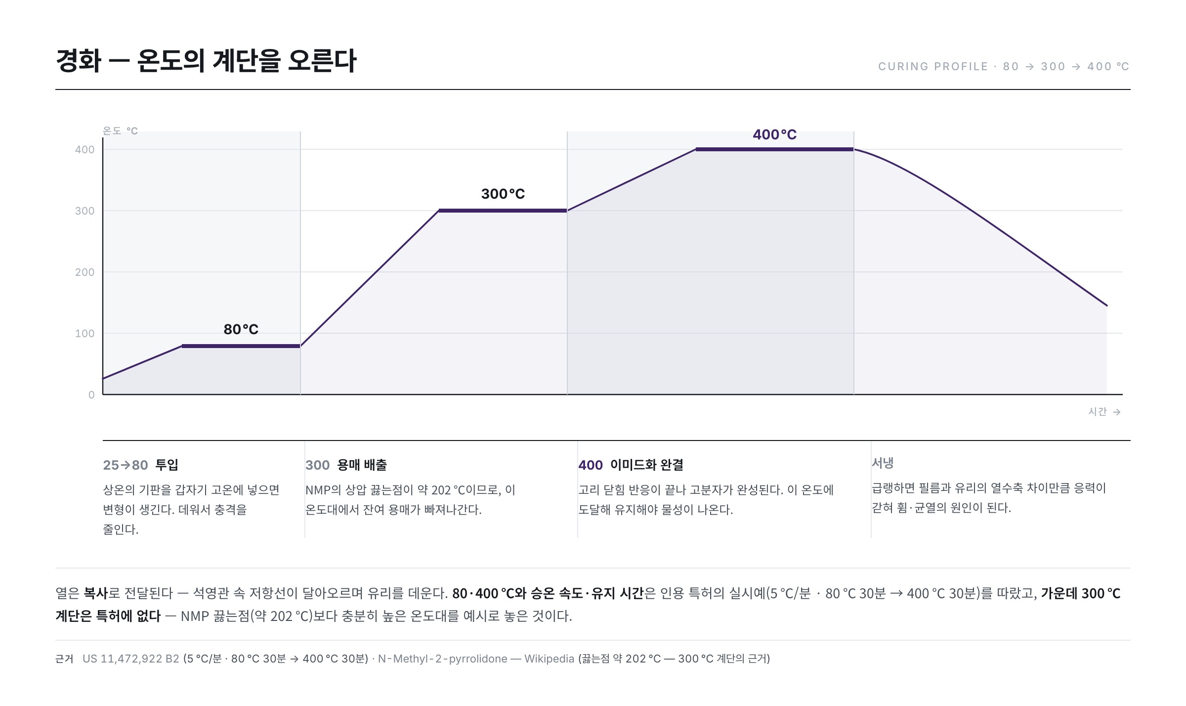
Last comes the oven. As seen in the previous article, curing is not drying but the step that completes the imidisation reaction, so the temperature is raised in stages like climbing a staircase rather than all at once. Placing what happens at each step alongside how the film thins reveals the intent of the profile. The thicknesses below are a simple conversion for a case starting at 15% solids and a 66.7㎛ wet film and ending at 10㎛.
| Step | What mainly happens | Cumulative solvent removal | Thickness (converted) |
|---|---|---|---|
| Just after coating | — | 0% | 66.7㎛ |
| Reduced-pressure drying | Low-temperature solvent evaporation | about 70% | 27.0㎛ |
| Loading, about 120℃ | Thermal shock relief, surface stabilisation | — | — |
| About 350℃ | Residual solvent expelled, imidisation begins | about 90% | 15.7㎛ |
| About 450℃ | Imidisation completed (ring closure) | 100% | 10.0㎛ |
| Cooling | Minimising residual stress | — | 10.0㎛ |
Let us look at the rationale for each step.
- Loading at about 120℃ — putting a room-temperature substrate straight into high heat causes abrupt phase change and deformation. Starting from a moderately warmed state reduces the shock. This is the same intent as the 5℃/min ramp and the 80℃ hold specified in the patent cited last time (US 11,472,922 B2).
- The 350℃ region — solvent evaporation. Since NMP boils at about 202℃, residual solvent is definitively driven out in this range. If reduced-pressure drying removed 70%, this step takes it to about 90%.
- The 450℃ region — imidisation completed. Ring closure finishes and the polymer is complete. Reaching and holding this temperature is what delivers the target properties.
- Cooling — done slowly. Quenching locks in stress equal to the thermal shrinkage difference between film and glass, causing bow and cracks. As calculated in the previous article, a large expansion mismatch produces stress on the order of 100 MPa, so the cooling curve is designed to minimise it. Even the cooling air passes through clean filters.
Whether the profile ran properly is judged by the degree of imidisation. Tracking the ratio of the imide ring peak to the amic acid peak by infrared spectroscopy shows in real time how far the reaction has progressed during the ramp ("In situ FTIR analysis for the determination of imidization degree of polyimide precursors," Polymer 238, 124416 (2022) · "Thermal imidization behaviors of poly(amic acid)…," Vibrational Spectroscopy 106, 103007 (2020)). An under-reacted film may look fine but will belatedly release water and residual solvent in a later anneal and lift the barrier layer.
Heating is by radiation. Current through a resistance wire inside a quartz tube makes it glow, and that heat reaches the glass as radiation. Heating without contact means less contamination, and dividing the oven into zones makes profiles easy to shape.
Five ways thickness goes astray
Most defects in the PI process converge on "the thickness differs from place to place". Each cause prints a different pattern, so the pattern narrows down the culprit.
| Cause | Pattern produced | Check and response |
|---|---|---|
| Pump pulsation | Periodic stripes perpendicular to travel | Compare pulsation period with stripe pitch; damper or pump change |
| Nozzle gap deviation | Long lines along the travel direction | Measure the gap, clean the lip, reassemble the nozzle |
| Travel speed variation | Thickness bands confined to accel/decel zones | Move accel/decel zones outside the effective coating area |
| Uneven vacuum exhaust | Mottle and bubble marks biased toward the exhaust | Multi-step exhaust flow, map pressure inside the chamber |
| Change in solution state | Thickness shifts as a whole by day or lot | Regular viscosity and solids measurement, degassing and filter cycles |
As the table shows, the response is mostly identifying the cause by measurement. Thickness itself is checked by optical metrology such as an ellipsometer (Ellipsometry) and the values are mapped onto substrate coordinates to reveal the pattern.
Inspection and repair — do not trust what you made
A cured PI film must pass optical inspection before the next layer. The surface is scanned for bubbles, particles, protrusions, thickness mottle and edge condition, and the coordinates of any defect are recorded (automated optical inspection, AOI).
What is interesting is that this is not the end: there is a repair step. Small bubbles or protrusions are burned flat by laser or removed physically, saving the substrate. If unrepairable defects exceed a set count, the substrate is not sent on. Exactly as the manufacturing adage says — defects get more expensive the further downstream they are found — a defect caught at the PI step is far cheaper than one found after the transistors are complete.
What the floor watches as numbers
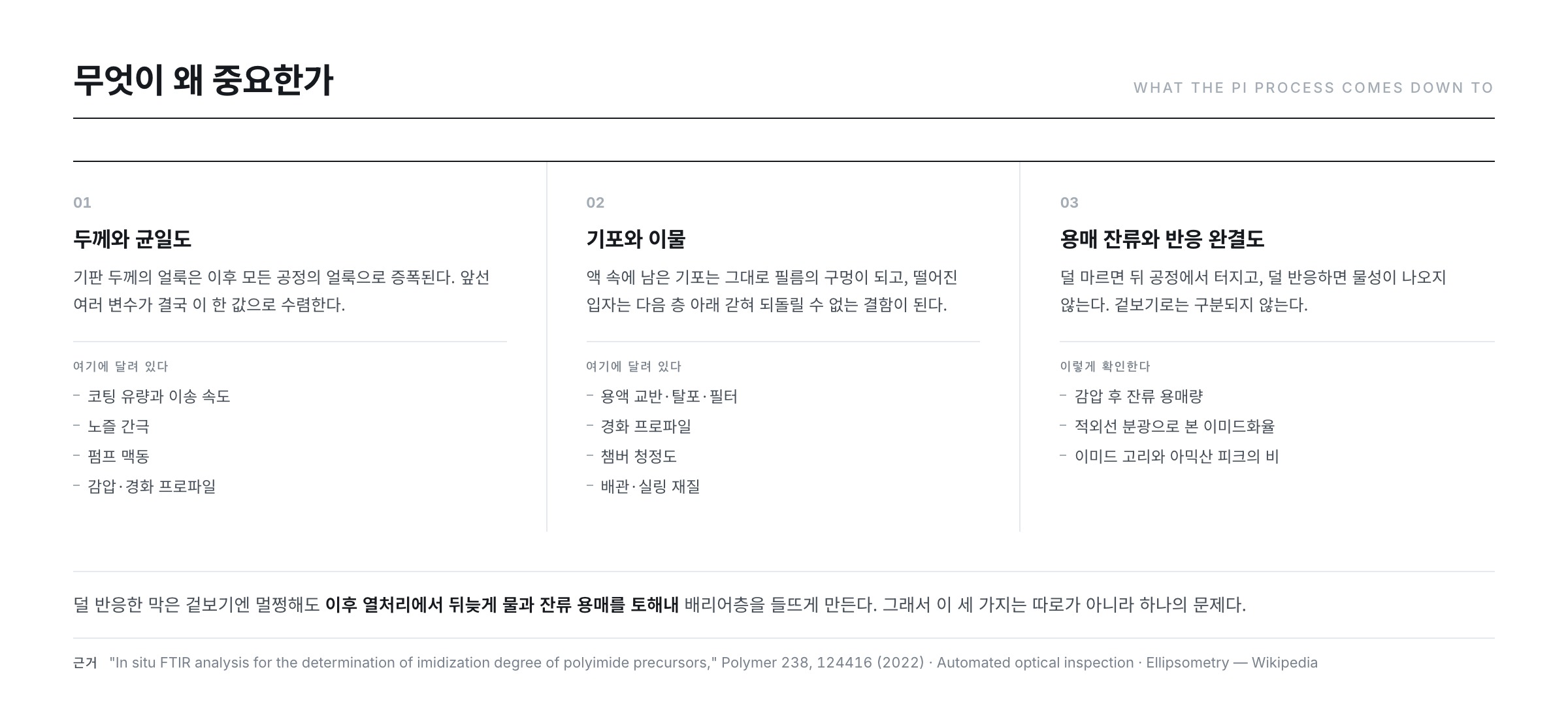
The control items converge into three branches.
- Thickness and uniformity — mottle in substrate thickness is amplified into mottle in every subsequent process. Coating flow and speed, nozzle gap, pump ripple, vacuum and cure profiles all converge on this single value.
- Bubbles and particles — managed as an allowed count and allowed size per defined area (one large substrate). Solution management (stirring, degassing, filtering), the cure profile and chamber cleanliness bear directly on this.
- Residual solvent and reaction completion — how much remains after vacuum drying, whether imidisation is complete after curing. Under-dried film bursts later; under-reacted film misses its properties.
The sum of all this is a lead time of 1.5~2 days. As the table showed, coating itself takes 17~50 seconds and vacuum drying a few minutes, but curing, inspection, cleaning and the waiting in between accumulate until a single substrate spends nearly two days in this section. That is why much of process improvement is not "making equipment faster" but "reducing the waiting".
Next article
The substrate is now complete. From the next article (Part 4) we move to the thermal processing chapter — starting with why the hydrogen hidden inside the first silicon film must be driven out as soon as it is deposited. If it is not, the film literally "bursts" in the laser step that follows.
References
- US 6,966,949 B2 — Apparatus and method for drying under reduced pressure, and coating film forming apparatus : varying exhaust flow in at least two steps to hold peripheral shape and thickness uniformity
- US 8,203,689 B2 — Reduced-pressure drying method, method of manufacturing functional film… : optimising evaporation rate per liquid and evening out vapour pressure distribution
- US 7,437,832 B2 — Reduced pressure drying apparatus : bubbles near the exhaust port → local swelling → thickness non-uniformity → display defects
- EP 2186848 A1 — Process for production of polyimide film, and polyamic acid solution composition : degassing and pre-drying of polyamic acid solution under reduced pressure
- US 11,472,922 B2 — Polyimide film, flexible substrate using same, and flexible display : 15~20% solids, slit coating example, 5℃/min ramp and two-step cure
- "Minimum wet thickness in extrusion slot coating," Chemical Engineering Science 47, 1703 (1992) : the thinnest wet film slot coating can make
- "Low-flow limit in slot coating: Theory and experiments," AIChE Journal 46, 1907 (2000) : the low-flow limit at which the coating bead breaks
- "A review of the operating limits in slot die coating processes," AIChE Journal 62, 2508 (2016) : operating limits and a map of defects
- "The Effect of Bead Vacuum on Slot Die Coating," International Polymer Processing 24, 157 (2009) : widening the stable window with bead vacuum
- "Bubble Defect Generation Mechanism in Slot Die Coating of High-Viscosity Fluids," ACS Applied Materials & Interfaces 16, 11890 (2024) : how bubble defects arise in viscous solutions
- "In situ FTIR analysis for the determination of imidization degree of polyimide precursors," Polymer 238, 124416 (2022) · "Thermal imidization behaviors of poly(amic acid)…," Vibrational Spectroscopy 106, 103007 (2020) : real-time tracking of imidisation during the ramp
- Clausius–Clapeyron relation · Trouton's rule · N-Methyl-2-pyrrolidone — Wikipedia : basis of the reduced-pressure boiling point table and the atmospheric boiling point of NMP (about 202℃)
- Automated optical inspection · Ellipsometry · PTFE · FFKM — Wikipedia : optical inspection and thickness metrology, chemically resistant piping and seals