In the previous article we looked at "why we bake" — to drive hydrogen out before the laser arrives. This article is about "what we bake with." Thermal processing equipment may look like a large oven from the outside, but inside it sits an entire three-axis trade-off: how many substrates at once, how fast, and up to what temperature.
Three siblings — batch, in-line and single-substrate
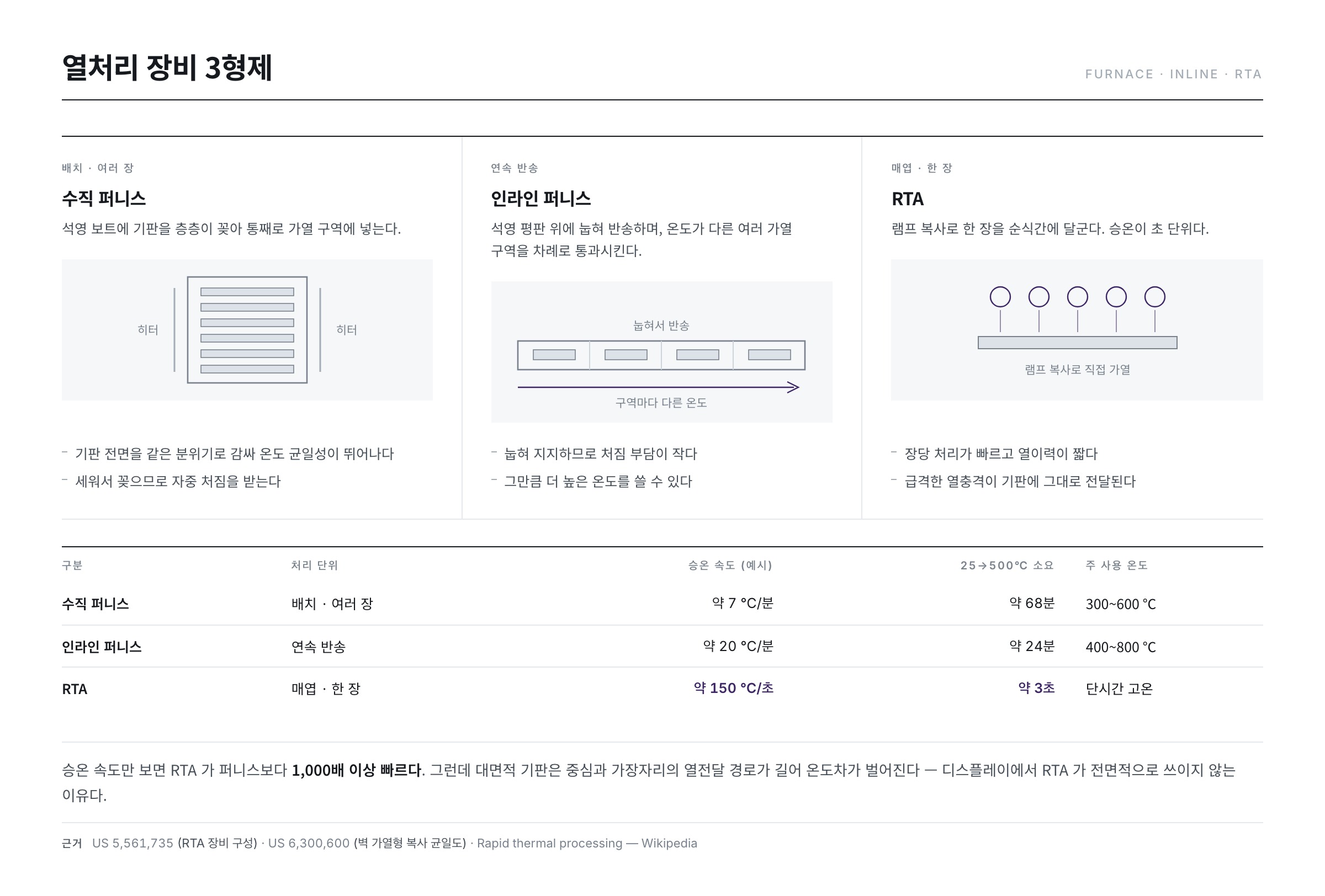
1. Vertical furnace — many at once
The most classical form. Substrates are slotted in layers into a quartz boat, and the whole assembly goes into the heating zone to bake. The structure is simple: loader/unloader, transport, boat, heaters and controls.
- Strengths — the whole substrate surface is wrapped in the same ambient, giving excellent temperature uniformity. Processing many substrates at once secures throughput per hour even for a long process.
- Weaknesses — the thermal mass is large, so heating and cooling are slow. Substrate deformation also caps the usable temperature (display work sits roughly at 300–600 °C, against the 1000 °C class of semiconductor processing), so a lower temperature must be compensated with a longer time. Process time grows as a result.
- The larger the substrate, the more awkward it becomes to handle vertically — another limitation.
2. In-line furnace — laid flat and flowed through
The answer that emerged for the era of large substrates. Rather than standing substrates up, they are laid flat on a quartz plate and transported through a series of heating zones (TCM, Temperature Control Module) held at different temperatures. It comprises loader/unloader, transport, heating modules, collection and controls.
- Supported flat, the burden of sag and deformation under its own weight is smaller, allowing higher temperatures (roughly the 400–800 °C range).
- Substrates flow continuously in one direction, which suits line flow and favours large-area glass.
- In exchange the equipment becomes long, and the temperature profile of each zone must be maintained precisely.
3. RTA — one substrate, in seconds
RTA (Rapid Thermal Annealing) is an entirely different idea. Instead of baking many substrates for a long time, it brings a single substrate to target temperature within seconds. Heating comes in two broad families: arrays of infrared lamps heating by radiation, and heated nitrogen gas blown uniformly through a shower head. Structures that keep the chamber wall itself hot to improve radiation uniformity are also documented in patents.
- The ramp is extremely fast, which favours shallow junction formation — the point is to activate dopants without giving them time to diffuse.
- Being single-substrate, per-plate processing is quick and activation efficiency is high.
- In exchange the abrupt thermal shock is transmitted straight into the substrate. Managing glass bending and warpage is this tool's homework.
The three tools in numbers
Comparing "fast" and "slow" in words alone gives no feel for it. Inserting representative ramp rates and computing the time to go from 25 °C to 500 °C makes the gap plain.
| Aspect | Vertical furnace | In-line furnace | RTA |
|---|---|---|---|
| Processing unit | Batch (many plates) | Continuous transport | Single plate |
| Typical ramp rate | about 7 °C/min | about 20 °C/min | about 150 °C/s |
| 25 → 500 °C | about 68 min | about 24 min | about 3 s |
| Working temperature | 300–600 °C | 400–800 °C | High, briefly |
| Temperature uniformity | Very good | Good (zone control needed) | Moderate (radiation-dependent) |
| Thermal budget | Large | Medium | Small |
| Main risk | Process time, chamber contamination | Equipment length, zone variation | Thermal shock, warpage |
On ramp rate alone, RTA is more than a thousand times faster than a batch furnace. That difference is not merely "quick" — it changes the character of the process itself.
Two kinds of temperature curve — thermal budget as a bank account
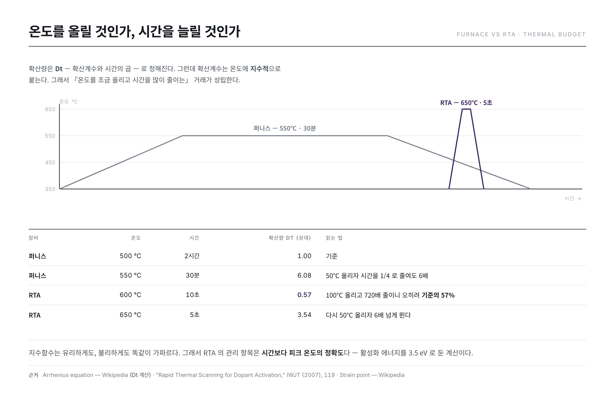
- The furnace curve is gentle and long; the RTA curve is short and sharp.
- The key concept is thermal budget — the total "temperature × time" a device has experienced.
- Exceed the budget and dopants spread, the substrate deforms, and films already made degrade.
Even for the same goal (dopant activation, say), the low-and-slow route and the hot-and-brief route consume different totals of thermal budget. "Raise the temperature, or extend the time?" — the choice of thermal processing equipment is ultimately an answer to that question.
Why short and hot wins — the Arrhenius arithmetic
Intuitively, raising the temperature ought to make diffusion worse. In practice the opposite comes out. The reason is that the diffusion coefficient responds to temperature exponentially while it responds to time only linearly.
diffusion ∝ D × t, D ∝ exp( −activation energy / kT )
Setting the diffusion activation energy at 3.5 eV and computing gives the following, with a furnace at 500 °C for 2 hours as the baseline (1.00).
| Condition | Temperature | Time | Relative diffusion (Dt) |
|---|---|---|---|
| Furnace | 500 °C | 2 hours | 1.00 (baseline) |
| Furnace | 550 °C | 30 min | 6.08 |
| RTA | 600 °C | 10 s | 0.57 |
| RTA | 650 °C | 5 s | 3.54 |
Look at the third row. Raising the temperature by 100 °C and cutting the time by a factor of 720 drops diffusion to 57 % of the baseline. Supplying the energy needed to activate dopants while denying them the time to spread — that is RTA's reason for existing.
At the same time, the second and fourth rows are a warning. Raise the temperature a little further and diffusion climbs quickly even in a short time. An exponential is equally steep in your favour and against you. That is why the controlled variable for RTA is peak temperature accuracy rather than time.
The price of fast heating — how much can glass take?
Nothing is free. Rapid heating creates temperature differences between front and back, and between centre and edge, and that difference immediately becomes thermal stress. In a constrained thin plate, the stress produced by a temperature difference ΔT is estimated roughly as follows.
stress σ ≈ E · α · ΔT / (1 − ν)
Here E is the elastic modulus, α the coefficient of thermal expansion and ν Poisson's ratio. Inserting typical values for alkali-free display glass (E ≈ 73 GPa, α ≈ 3.2 × 10⁻⁶/K, ν ≈ 0.23) gives this.
| ΔT across the substrate | Thermal stress | Meaning |
|---|---|---|
| 10 °C | about 3.0 MPa | Comfortable margin |
| 50 °C | about 15.2 MPa | Warpage and alignment error need managing |
| 100 °C | about 30.3 MPa | Warpage and breakage risk zone |
Stress grows linearly with ΔT. So designing an RTA tool is as much a fight over "how narrowly the temperature difference inside the substrate is held while ramping" as over "how fast it ramps." Lamp array density, gas shower uniformity and chamber wall temperature all serve that single goal.
And the problem worsens as the glass grows. At the same ramp rate, a large-area substrate has a longer heat path between centre and edge, so ΔT widens. That is the practical reason RTA is not used as universally in display lines as it is in semiconductor lines.
What matters is after it cools — designing the down-ramp
Discussions of thermal processing usually look only at the way up. But the way down creates ΔT just the same. Cooling is arguably harder to control, because heat is being taken away rather than actively supplied. If the surface cools first and the interior later, that lag remains inside the glass as residual stress.
Two temperatures specific to glass appear here. One is the annealing point, at which the material is soft enough for stress to relax on its own; the other is the strain point, below which the shape is effectively frozen. The design principle is simple — keep the maximum process temperature below the strain point.
What happens if you break it? Above the strain point the glass deforms plastically, little by little, under its own weight and internal stress. Even at an invisible scale this is a problem. If substrate dimensions shift slightly, subsequent exposure steps fail to align and the patterns of successive layers no longer register. This is precisely the physical basis for the repeated claim, in part 4 and here, that display processing cannot use 1000 °C the way semiconductor processing does. It is a constraint glass has and a silicon wafer does not.
Real recipes therefore hold at the target temperature for a set time and then come down deliberately slowly through the region near the strain point. Lowering the cooling rate narrows ΔT and reduces residual stress and warpage together, but it occupies the tool for longer and cuts throughput. Time saved on the ramp up is spent again on the way down, so the true duration of a thermal process is often set by the cooling curve rather than the peak temperature.
The purpose picks the tool
Which of the three tools to use is not a matter of taste but of what the thermal step is trying to do. Listing the places heating appears in backplane processing, by purpose, reveals the logic of the choice.
| Process purpose | What is needed | Thermal budget margin | Suitable tool |
|---|---|---|---|
| Dehydrogenation (part 4) | Draw hydrogen slowly out of the whole film | Generous | Furnace — slow ramping is an advantage |
| Dopant activation (part 8) | Give energy but block diffusion | Very tight | RTA — short and hot |
| Densifying an insulating film | Heat the whole film evenly | Moderate | In-line furnace |
| Hydrogenation (repairing grain boundaries) | Introduce hydrogen at low temperature | Generous | Furnace or plasma treatment |
Note that the same "heating" carries opposite requirements. Dehydrogenation needs atoms to have time to move and escape, so slower is better; activation must deny them that time, so faster is better. There is no such thing as a "good thermal tool" — only the tool that fits this step.
The hidden cost of batch processing — throughput is per lot, not per hour
Judged by processing time per substrate, the table above suggests batch tools are not at a disadvantage, because many plates are baked at once. Placed in a production line, however, batch processing carries three costs the table does not record: time spent waiting, risk bound together, and results that surface late.
First, the waiting. A batch does not depart until every slot is filled. If substrates arrive at five-minute intervals, filling twenty slots alone takes 95 minutes, and the first substrate spends all of it doing nothing. Taking the ramp rate above (7 °C per minute) to give 68 minutes from 25 °C to 500 °C, then assuming a 60-minute soak and 90 minutes of cooling for a 218-minute cycle, the arithmetic runs as follows.
| Batch size | Wait until the lot is full | Effective time per substrate | Total lead time for the first plate | Loss if one run goes wrong |
|---|---|---|---|---|
| 10 plates | 45 min | 21.8 min | 263 min | 10 plates |
| 20 plates | 95 min | 10.9 min | 313 min | 20 plates |
| 40 plates | 195 min | 5.5 min | 413 min | 40 plates |
| Single-substrate (for comparison) | None | A few minutes at most | Almost the same as the process time | 1 plate |
Doubling the batch halves the time per substrate, but the lead time and the size of the loss double along with it. Nor is the substrate simply idle while it waits. Its surface remains exposed to moisture and oxygen in the air, and if it has just come out of a film process, its properties drift in the meantime. That is why many lines set a queue-time limit on both sides of a thermal step.
The third cost is quieter. The result of a batch is not visible on the spot; it emerges only at the inspection after the next process. If the following batch is already running under the same settings by then, a single mis-set parameter costs not one batch but several. This is why single-substrate tools get chosen on real lines despite a higher cost per plate — not because they are faster, but because they are easier to undo.
Measuring the temperature is the harder part
So far temperature has been treated as a value known exactly. On the floor, measuring it is itself the problem.
The most reliable method is attaching a thermocouple directly to the substrate. Accurate, but unusable on production substrates — the contact is contamination, and attaching and removing it is impossible in single-substrate processing. So the standard practice became periodic measurement on a dummy substrate with thermocouples attached, using the result to calibrate the tool's setpoints. In other words, during production the temperature is not measured directly; the tool runs on values measured in the past.
To measure without contact, a radiation thermometer reads the infrared the object emits. There is a trap here. This method needs the target's emissivity to convert to temperature, and the emissivity of silicon varies with temperature, doping concentration, surface condition and film thickness. With several thin films stacked on top, interference makes the value waver further. In a process that finishes in seconds, like RTA, this error translates directly into a difference in the result.
In short, the precision of thermal processing hangs on the precision of the thermometer, not of the heater. Recall from the Dt table above that 50 °C changed the diffusion by a factor of six. If the temperature is being read 20 °C wrong, no amount of care in composing the recipe means anything.
Ambient and cleanliness — what surrounds it
Thermal processing is not only about "heating" but about what ambient you heat in. A hot silicon surface forms an oxide the moment it meets oxygen, so the chamber is generally filled with an inert gas such as nitrogen to prevent unwanted oxidation. In processes that drive gas out, such as dehydrogenation, the exhaust design matters too — hydrogen that escapes and then wanders inside the chamber can be reabsorbed into the film.
The hydrogen effusion seen in part 4 is itself not simple evaporation. During the ramp, Si-H bonds break and rearrange, hydrogen clusters and then leaves — a multi-stage behaviour in which how slowly you pass through which temperature range governs the final residual hydrogen. Set the ramp segment carelessly fast and the surface hardens with hydrogen still trapped inside the film.
One curiosity. In ELA processing, designs that block contact with the atmosphere entirely before and after crystallisation are also registered as patents — one is titled "method for crystallizing semiconductor material without exposing it to air." Evidence of how sensitive ambient control is between thermal processing and crystallisation.
Another: batch furnaces accumulate sublimated deposits and particles on chamber walls and quartz boats. Miss the periodic cleaning and bake-out schedule and yield is quietly eroded — backside contamination or particle defects begin creeping up one day. RTA, processing one plate briefly at a time, is comparatively favourable on ambient cleanliness.
What the floor watches — three control points
- Temperature uniformity across the substrate — harder the larger the area. Position-to-position temperature differences become differences in residual hydrogen and degree of activation, and finally appear as mura on the screen. Periodic profile measurement, with thermocouples attached to a dummy substrate, is the standard practice.
- Bending and warpage — especially important in fast-ramp methods such as RTA. As the table showed, a ΔT of 100 °C imposes stress of the 30 MPa class. A warped substrate misaligns in subsequent exposure and the pattern shifts. A textbook example of thermal process quality surfacing as a problem several steps later.
- Thermal budget management — tracking the cumulative heat a substrate has received across the whole process. If heating occurs again downstream, the temperature and time upstream must be reduced to keep the total in balance. The Dt table above is the basic tool for that calculation.
With that, the substrate has shed its hydrogen and is firmly prepared. From the next article (part 6) we finally reach the heart of LTPS: ELA crystallisation.
References
- "Bond switching, Si-H cluster formation and hydrogen effusion upon thermal annealing," Thin Solid Films 271, 151 (1995) : multi-stage behaviour of Si-H rearrangement and hydrogen effusion during the ramp
- "Thermal annealing and hydrogenation of chlorinated hydrogenated amorphous silicon," Thin Solid Films 147, 285 (1987) : relation between annealing conditions and the state of hydrogen in the film
- "Junction Formation in Silicon by Rapid Thermal Annealing," in Rapid Thermal Processing (1993), 169 : shallow junction formation by RTA and its thermal budget advantage
- "Rapid Thermal Scanning for Dopant Activation for Advanced Junction Technology," IWJT (2007), 119 : separating activation from diffusion under fast ramping
- US 5,561,735 — Rapid thermal processing apparatus and method : basic RTA tool configuration and ramp control
- US 6,300,600 — Hot wall rapid thermal processor : heating the chamber wall to secure radiation uniformity
- US 6,881,615 B2 — Method for crystallizing semiconductor material without exposing it to air : blocking the atmosphere before and after crystallisation
- Rapid thermal processing — Wikipedia : principles of RTA/RTP, lamp heating, shallow junctions
- Arrhenius equation — Wikipedia : the temperature dependence behind the Dt table above
- Thermal stress — Wikipedia : stress produced by temperature differences and constraint conditions
- Annealing (glass) — Wikipedia : removing residual stress by slow cooling
- Strain point — Wikipedia : the temperature at which shape freezes — the basis for the process temperature ceiling
- Annealing (materials science) — Wikipedia : recovery and recrystallisation principles
- Low-temperature polycrystalline silicon — Wikipedia : the low-temperature constraint and LTPS process flow