Every process step so far has had one thing in common. Coating, heat treatment, laser annealing, doping — all of it happened inside a vacuum chamber. The steps that remain (deposition and etching) simply do not exist without vacuum and plasma. As the opening instalment of the deposition chapter, this part looks at the stage machinery itself.
What is vacuum?
Vacuum comes from the Latin vacua, "an empty place". An ideal vacuum has zero pressure, but no such thing exists in reality. In engineering terms it means a space at a pressure below atmospheric, and it is graded by how empty it is (Vacuum).
Numbers make it concrete. From the ideal gas law, the molecular number density is the pressure divided by the product of the Boltzmann constant and the temperature:
number density n = P ÷ (k × T) (k = 1.381×10⁻²³ J/K)
Put in 20 °C and one atmosphere (101,325 Pa) and you get about 2.5×10¹⁹ molecules in every cm³. Creating a vacuum means reducing that number.

Why vacuum is necessary
Vacuum provides three things.
- A clean space — without oxygen, moisture and dust in the air, only the intended material becomes film. Residual gas ends up as film impurity.
- Low pressure that favours evaporation — at low pressure a material vaporises easily, and the vaporised atoms can travel straight to the substrate without colliding with other molecules. Deposition only works when this "mean free path" is longer than the chamber.
- A special environment — lowering the pressure lowers the boiling point. The reduced-pressure drying seen in Part 3 relied on exactly this.
The arithmetic of mean free path — reading vacuum as a number
What does "good vacuum" actually mean? The answer is the average distance a gas molecule flies before hitting another molecule — the mean free path (λ) (Mean free path). In the hard-sphere model it is calculated as:
λ = k·T ÷ (√2 × π × d² × P) (d = effective molecular diameter)
Let us put room-temperature (20 °C) nitrogen into it. Taking the effective diameter of a nitrogen molecule as 0.37 nm and varying only the pressure gives the table below. The same table also lists the monolayer formation time — how long a freshly cleaned surface takes to be covered by one layer of residual gas, obtained by dividing the molecular impingement flux P ÷ √(2π·m·k·T) by the surface site density (about 10¹⁵ per cm²). It assumes a sticking probability of one, so it is the shortest possible time.
| Pressure | Grade | Number density (cm⁻³) | Mean free path λ | Monolayer time |
|---|---|---|---|---|
| 760 Torr (atmosphere) | — | 2.5×10¹⁹ | 66 nm | 3.4 ns |
| 1 Torr | low / medium vacuum | 3.3×10¹⁶ | 50 μm | 2.6 μs |
| 1 mTorr (10⁻³ Torr) | threshold of high vacuum | 3.3×10¹³ | 50 mm | 2.6 ms |
| 10⁻⁶ Torr | high vacuum | 3.3×10¹⁰ | 50 m | 2.6 s |
| 10⁻⁹ Torr | ultra-high vacuum | 3.3×10⁷ | about 50 km | about 43 min |
This table explains almost every judgement made in vacuum processing.
- At atmospheric pressure nothing can fly anywhere. λ is 66 nm — one thousandth of a human hair. Even if an atom is knocked off a target, it collides with air before travelling a single micrometre.
- Around 1 mTorr is the fork in the road. λ is 50 mm — the same order as the target-to-substrate distance inside the chamber. In this regime particles arrive after a few collisions, so directionality blurs slightly but the coverage across the substrate becomes even. This is why the sputtering of Part 10 uses this pressure band.
- Below 10⁻⁶ Torr is the world of pure line-of-sight. λ is 50 m — two orders of magnitude larger than the chamber. An atom leaving the source reaches the substrate without a single collision, which is also why nothing deposits in shadowed regions.
- Cleanliness has a time limit. At 10⁻⁶ Torr a freshly cleaned surface is covered by residual gas within three seconds. Handling a genuinely clean surface means going down to ultra-high vacuum to buy minutes instead of seconds. This is where the importance of controlling the queue time between pre-deposition cleaning and deposition comes from.
Vacuum is not made with a single pump
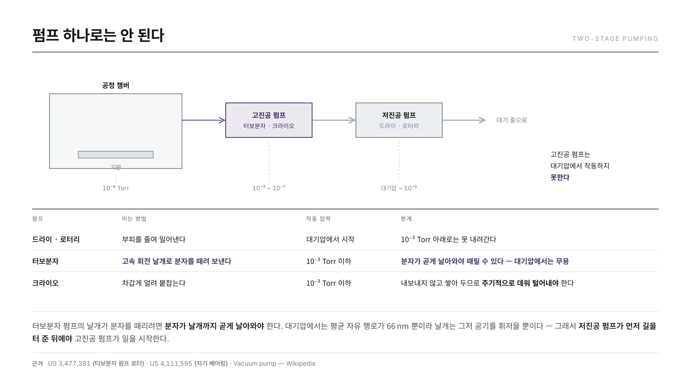
A vacuum tool is a more complex plumbing system than it looks: the chamber, a set of valves (roughing, main, backstreaming prevention, vent), gauges for each pressure band, and two kinds of pump.
Why two pumps? Because a high-vacuum pump cannot operate at atmospheric pressure. The table above shows why. A turbomolecular pump is a device in which fast-rotating blades knock molecules in one direction, and for that to work a molecule must not collide with another molecule before reaching a blade — that is, λ must exceed the blade spacing. At atmospheric pressure λ is only 66 nm, so the blades merely stir the air. The chamber is therefore roughed out first with a low-vacuum pump (rotary or Roots type), after which the main valve opens and the high-vacuum pump takes over.
Pumps also divide by operating principle — transfer types that push gas out (rotary, Roots, turbomolecular) and capture types that trap and hold gas (cryo, ion, sorption) (Vacuum pump).
| Pump | Class | Operating principle | Main pressure range |
|---|---|---|---|
| Rotary vane | Transfer | An eccentric rotor compresses gas and expels it to atmosphere | atmosphere → 10⁻³ Torr |
| Roots (mechanical booster) | Transfer | Two meshing rotors push large gas volumes | 10 → 10⁻⁴ Torr |
| Turbomolecular | Transfer | High-speed blades impart directional momentum to molecules | 10⁻³ → 10⁻¹⁰ Torr |
| Cryogenic | Capture | Gas condenses and adsorbs on cryogenic surfaces | 10⁻³ → 10⁻¹⁰ Torr |
| Sputter ion | Capture | Ionised gas is buried in the electrode | 10⁻⁵ → 10⁻¹¹ Torr |
The lineage of the turbomolecular pump is interesting. The idea of pushing molecules with rotating blades is old, but the keys to making it practical were the blade geometry and how to support the shaft. A rotor construction with radially extending blades twisted so as to overlap was set out in patent form (US 3,477,381 — Turbo-molecular pump), and later the introduction of magnetic bearings that levitate the shaft without contact removed the risk of lubricant backstreaming into the chamber (US 4,111,595 — Turbomolecular pump with magnetic mounting). The oil-free vacuum that semiconductor and display processes demand stands on this lineage.
Capture pumps have one decisive property: because they store gas inside rather than expelling it, they eventually saturate. That is why a cryopump has to be warmed periodically to release what it caught — a regeneration step whose duration comes straight out of tool availability.
Eyes that read pressure — one instrument is not enough
Gauges cannot be of a single type either. As the table shows, the pressures to be handled span twelve decades from atmosphere down to 10⁻⁹ Torr, and no physical quantity responds linearly across that whole range.
- Thermal conduction gauges (Pirani, thermocouple) — they exploit the fact that the heat drawn away from a heated fine wire by the gas varies with pressure. The principle had already been worked into an instrument for measuring small pressure changes in the 1930s ("The Pirani Gauge for the Measurement of Small Changes of Pressure," Phys. Rev. 37, 1102 (1931)). At very low pressure, however, too little gas remains to carry heat and sensitivity is lost.
- Capacitance diaphragm gauges — the deflection of a thin membrane under pressure is read as a capacitance. Their great advantage is independence from gas species, which makes them the reference for process pressure control.
- Ionisation gauges — gas is ionised by electrons and the resulting ion current is converted to pressure. This is the standard for high and ultra-high vacuum, but early forms had a limit: soft X-rays generated when electrons struck the electrode produced a current at the collector, creating a floor that read higher than the true pressure. Replacing the collector with a fine wire lowered that floor, and the resulting design became the archetype of today's high-vacuum gauges ("Extension of the Low Pressure Range of the Ionization Gauge," Rev. Sci. Instrum. 21, 571 (1950)).
Plasma — the fourth state of matter

If the vacuum chamber is the stage, the actor that actually works on it is plasma. Plasma is an ionised gas in which charged and neutral particles are mixed together, yet the densities of positive and negative charge are equal so that the whole is quasi-neutral on a macroscopic scale (Plasma (physics)).
It is commonly called the fourth state of matter, and most of the matter in the universe is in this state. Neon signs, fluorescent lamps, aurorae and the sun are all plasma. The name "plasma" and the property that charges within it oscillate collectively were established in studies of ionised gases in the late 1920s ("Oscillations in Ionized Gases," Phys. Rev. 33, 195 (1929)).
Why processes use plasma — a tale of two temperatures
There is only one reason: temperature. Breaking up a reactant gas takes energy, and doing it with heat alone would require hundreds to thousands of degrees Celsius. Glass substrates cannot take that.
Plasma sidesteps the problem, because electrons accelerated by the electric field collide with neutral gas molecules and dissociate them instead. The key point is that the electrons and the gas are at different temperatures. Converting temperature into energy exposes the gap:
1 eV = 1.602×10⁻¹⁹ J ÷ 1.381×10⁻²³ J/K ≈ 11,600 K / room temperature 293 K ≈ 0.025 eV
| Species | Typical energy | Converted to temperature | Job in the process |
|---|---|---|---|
| Electrons | a few eV (e.g. 2 eV) | about 23,000 K | Dissociate and ionise molecules by collision — the trigger of chemistry |
| Ions | roughly 0.03–0.1 eV | a few hundred K | Pulled by the sheath potential to bombard the surface |
| Neutral gas | about 0.03 eV | a few hundred K (300–600 K) | Feedstock of the reaction and carrier of heat |
Electrons hotter than 20,000 K coexist in the same space with gas at a few hundred K. Thermodynamic equilibrium would never permit this, which is why such discharges are called non-equilibrium or low-temperature plasmas. Why does equilibrium not arrive? The answer is the mass difference.
- An electron is about 50,000 times lighter than a nitrogen molecule. In the same electric field only the electron is accelerated hard.
- When a light ball hits a heavy one it hands over almost no energy. The fraction transferred in an elastic collision is roughly twice the mass ratio — that is, about four parts in a hundred thousand (0.004%) per collision. No matter how often electrons collide, they cannot heat the gas.
- In inelastic collisions that break or ionise a molecule, however, the electron gives up its energy all at once. The energy therefore flows into chemistry rather than heat.
That is the whole idea of low-temperature plasma processing: heat only the electrons, not the gas, and get chemistry without heat. Thanks to it, films can be grown on glass at around 250–400 °C. In a real discharge the electron energy is not a single value but a broad distribution, and measuring that distribution with a probe and matching it against process conditions is the basic work of plasma diagnostics ("Langmuir probe diagnostics of electron energy distributions with optical emission spectroscopy in capacitively coupled rf discharge in nitrogen," J. Appl. Phys. 110 (2011)).
How plasma is generated
There are several ways to strike a plasma.
- DC discharge — a direct voltage is applied between two electrodes. Simple, but it cannot handle insulators: charge accumulates on the surface and the discharge stops.
- RF discharge (capacitively coupled) — high-frequency power is used. The industry standard frequency is 13.56 MHz, a band allocated internationally for industrial, scientific and medical use (ISM radio band). It took hold for the extremely practical reason that it is not a communication band, so interference regulation is lenient. Because the voltage polarity keeps reversing, charge does not build up even on insulating surfaces, which makes deposition and etching of insulating films possible.
- High-density plasma — inductive coupling (ICP), microwave, ECR, helicon and similar schemes raise the plasma density greatly. They can lower the electron temperature while raising density, giving less damage and better uniformity. A representative example is the ECR approach, which uses a magnetic field to bring electrons into resonance and sustain a dense plasma even at very low pressure ("Very-low-pressure deposition by electron cyclotron resonance plasma chemical vapor deposition method," J. Appl. Phys. 67, 6281 (1990)).
| Method | Power coupling | Plasma density | Ion energy control | Character |
|---|---|---|---|---|
| DC discharge | DC electrodes | Low | Tied to the applied voltage | Simple; insulators impossible |
| RF capacitive (CCP) | Parallel plate electrodes | Medium | Set by self-bias — tied to density | Insulating films possible; general purpose |
| High density (ICP, ECR) | Coil or microwave (+ separate substrate bias) | High | Decoupled from density and set independently | Low pressure, low damage, good uniformity |
The right-hand columns summarise why high-density plasmas appeared. In a capacitively coupled scheme, raising the power raises density and ion energy together, so the combination "vigorous chemistry, gentle ions" cannot be produced. Splitting plasma generation and substrate bias into separate supplies releases that constraint.
One phenomenon in RF discharges is worth knowing. Electrons are far lighter and faster than ions, so more of them reach the electrode. The electrode therefore charges negatively, producing a DC self-bias and a potential difference between plasma and electrode. That potential pulls ions towards the substrate — in deposition it is used to densify the film, and in etching it becomes the force that cuts vertically (we meet it again in Parts 14 and 15).
A double-edged sword — plasma damage
Plasma is not a cure-all. Ions carrying more than 20 eV can damage the film when they strike the substrate. Using the conversion above, 20 eV corresponds to a kinetic energy equivalent of about 230,000 K, far more than enough to break bonds in the silicon lattice. And because the reactions occur at low temperature, by-product gases are exhausted in an incompletely reacted state, loading the abatement system.
The balance between damage, density and uniformity therefore differs by method. DC gives low temperature with moderate damage, RF capacitive coupling gives medium density, and high-density plasmas such as ICP and ECR deliver low electron temperature, high density, very low damage and good uniformity. The stage machinery is chosen according to the purpose.
Common misconceptions
- "Vacuum is a space with nothing in it." — No. As the table shows, even the "high vacuum" of 10⁻⁶ Torr still holds 33 billion molecules per cm³. Vacuum is not a question of emptiness but of how much the remaining molecules get in the way.
- "Higher vacuum is always better." — No. Sputtering needs gas to sustain the plasma, so the pressure is deliberately raised back into the mTorr band. The target is not "as low as possible" but "whatever λ the process requires".
- "Plasma is hot." — The sun and arcs are, but the gas temperature of a processing low-temperature plasma is only a few hundred kelvin. Only the electrons are hot, and they are far too light to create a temperature you could feel.
- "A bigger pump means faster pumping." — Pumping speed is often set not by the pump but by the conductance of the plumbing. In high vacuum molecules bounce randomly off walls, so a narrow or long line throttles the system no matter how large the pump.
What the fab watches — three control points
- Base pressure and leaks — whether the chamber reaches the target pressure and then holds it. Measuring the rate of rise after valving off the pump distinguishes leakage from outgassing. A small leak shows up directly as film impurity.
- Plasma stability — if applied power, reflected power or pressure wanders, film thickness, stress and composition wander with it. Reflected power in particular reflects both the matching network and the chamber condition, so it is logged every run and read as a trend.
- Chamber cleanliness — deposits built up on the walls eventually flake off as particles. Regular chamber cleaning (plasma cleaning included) and disciplined part-replacement intervals are, in effect, yield management.
The stage and the actors are ready. In the next instalment (Part 10) we watch the first performance staged here — building metal wiring by sputtering.
References
- "Oscillations in Ionized Gases," Physical Review 33, 195 (1929) : the name "plasma" and the treatment of collective oscillation
- "The Pirani Gauge for the Measurement of Small Changes of Pressure," Physical Review 37, 1102 (1931) : the principle of thermal-conduction pressure measurement
- "Extension of the Low Pressure Range of the Ionization Gauge," Review of Scientific Instruments 21, 571 (1950) : lowering the measurement floor of the high-vacuum ionisation gauge
- "Very-low-pressure deposition by electron cyclotron resonance plasma chemical vapor deposition method," Journal of Applied Physics 67, 6281 (1990) : high-density plasma deposition at very low pressure
- "Langmuir probe diagnostics of electron energy distributions with optical emission spectroscopy in capacitively coupled rf discharge in nitrogen," Journal of Applied Physics 110 (2011) : measured diagnostics of the electron energy distribution
- US 3,477,381 — Turbo-molecular pump : rotor construction that pushes molecules with rotating blades
- US 4,111,595 — Turbomolecular pump with magnetic mounting : a configuration removing contact and lubrication via magnetic bearings
- Vacuum — Wikipedia : the definition of vacuum and its pressure grades
- Mean free path — Wikipedia : the definition and hard-sphere expression — the basis of the table in the text
- Vacuum pump — Wikipedia : transfer and capture pump types and their operating ranges
- Plasma (physics) — Wikipedia : the definition of plasma and quasi-neutrality
- ISM radio band — Wikipedia : why 13.56 MHz became the industrial standard frequency