In the previous installment we pulled the threshold voltage out three different ways. Three values came from one and the same curve, and what changed was not the device but the convention about where to read.
Threshold voltage answers the question "where does it turn on?". But there is one more question worth putting to a switch — how cleanly does it turn on and off. Two devices with the same threshold voltage can give entirely different answers to this one. One turns on all at once within a narrow span of voltage; the other turns on loosely, spread over a wide span.
This installment looks at the two numbers that measure that cleanliness: the slope of the subthreshold region, and the ratio of the on current to the off current. The first measures how steep the turning-on is, the second how far apart the on state and the off state sit.
The condition values in the text are examples meant to show how the calculation goes, not the specifications of any particular company. Every figure quoted was checked in the open literature, and the sources are left at the end of the article.
Subthreshold slope — the voltage it takes to move one decade
In #02 we put the transfer curve on a logarithmic axis. Of the four regions, the second — the subthreshold region — was a straight line. Taking the logarithm of an exponential function turns it into a straight line.
If it is a straight line, its slope can be written down as a single number. The Wikipedia "Subthreshold slope" article treats this region as one property of the current–voltage characteristics of a field-effect transistor and states that the current behaves log-linearly with respect to the gate voltage. That slope is called the subthreshold slope.
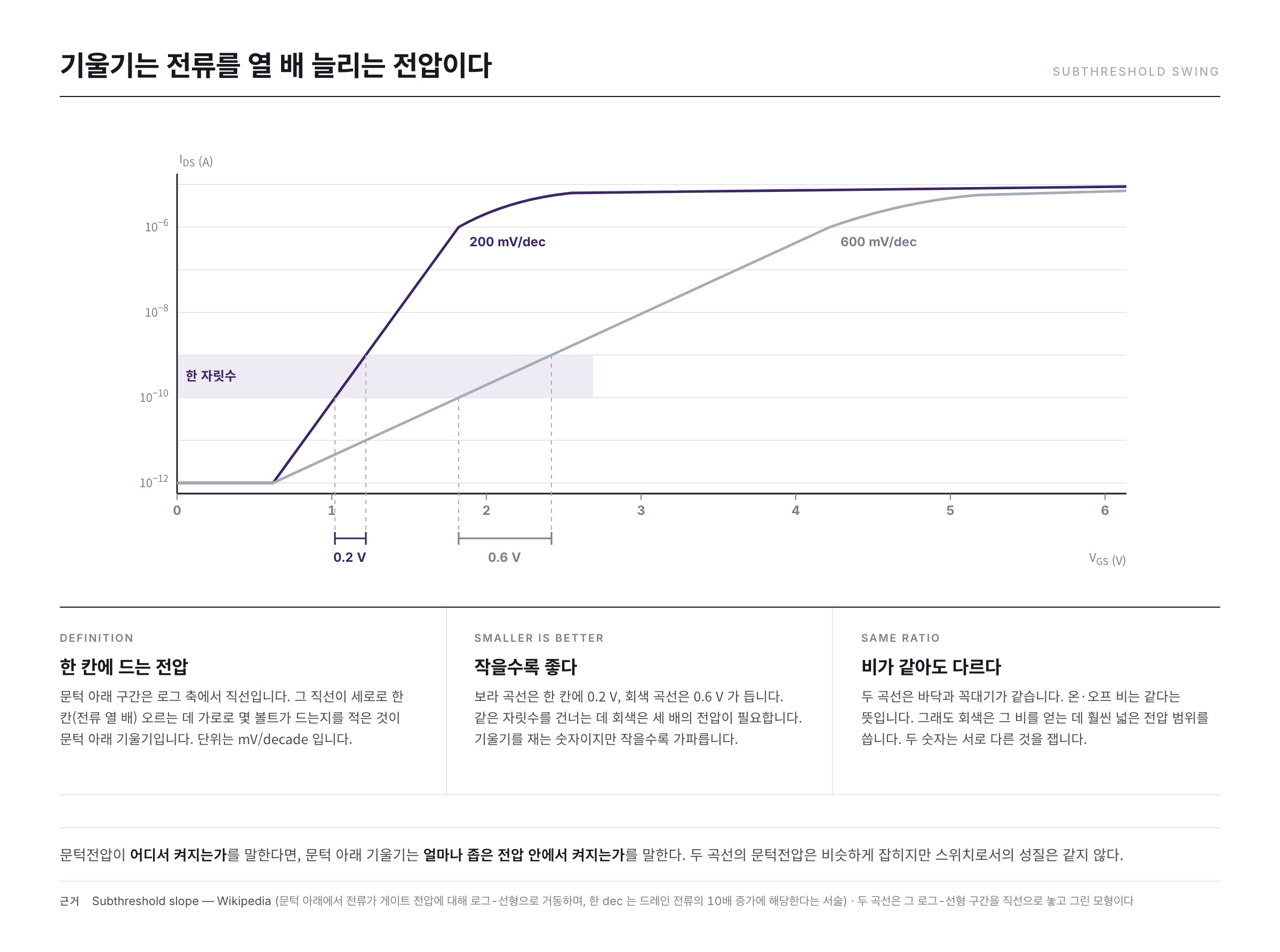
When the value is actually written down, what is used is not the slope itself but its reciprocal. That is the subthreshold swing, and its unit is mV/decade. The "Subthreshold slope" article defines the decade used here as a tenfold increase in the drain current.
The meaning then fits into a single line.
- Subthreshold swing = the gate voltage needed to raise the current tenfold
It is enough to read the unit out loud. At 60 mV/decade, every 0.06 V added to the gate voltage multiplies the current by ten. At 600 mV/decade, that same factor of ten costs 0.6 V.
It is called a slope, yet smaller is better
The name contains the word slope, but the smaller the value, the steeper the curve. That is because what gets written down is the reciprocal rather than the slope. It catches the eye the first time, so it is worth stating once.
Why the smaller side is the better one becomes plain once numbers go in. Suppose the current rises six decades on the way from the off state to the on state.
- A device at 100 mV/decade — 0.1 V × 6 = 0.6 V
- A device at 300 mV/decade — 0.3 V × 6 = 1.8 V
Three times the voltage for the same piece of work. The voltage it takes to switch the device on and off becomes the voltage range of the circuit that drives it, so this difference is precisely the difference in how little voltage is needed to switch reliably.
There is a floor that cannot be crossed
Here comes the fact at the centre of this installment. However well it is made, the subthreshold swing does not fall below a certain value at room temperature.
The expression carried by the Wikipedia "Subthreshold slope" article is this.
S = ln(10) · (kT/q) · (1 + Cd/Cox)
Cd is the depletion-layer capacitance, Cox the gate insulator capacitance, and kT/q the thermal voltage. Noting that the bracket cannot become smaller than 1, the minimum of this expression occurs when the bracket equals 1. The "Subthreshold slope" article writes that value as Smin = ln(10)·kT/q, calls it the thermionic limit, and states it as 60 mV/decade at a room temperature of 300 K.
Working it out directly
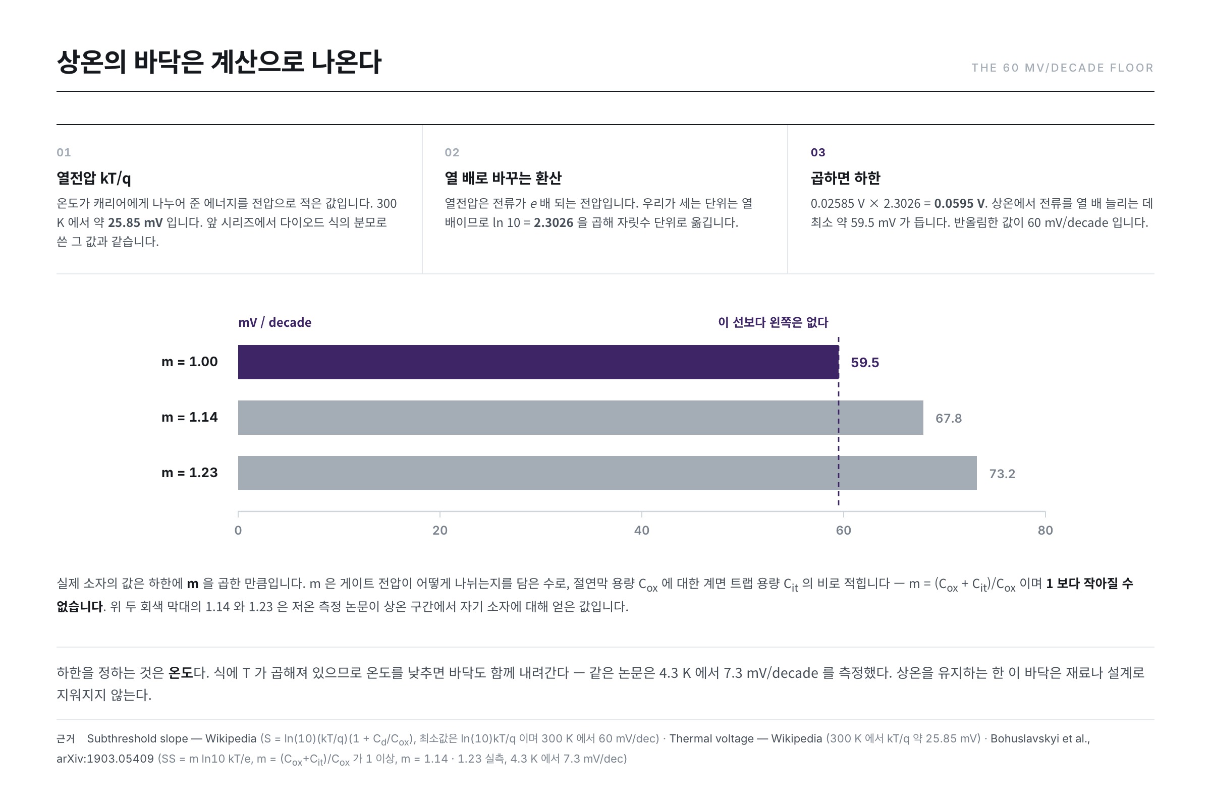
This number 60 is not something to memorise; it is one multiplication. The thermal voltage used in the earlier series carries over unchanged. The Wikipedia "Thermal voltage" article writes that kT/q is about 25.85 mV at 300 K (27 °C). This article assumes 300 K in its calculations.
- kT/q = 0.02585 V
- ln 10 = 2.3026
- 0.02585 × 2.3026 = 0.05952 V
About 59.5 mV. The 60 mV/decade the literature speaks of is that value rounded off.
Why ln 10 is multiplied in also takes one line to explain. The thermal voltage is the voltage that multiplies the current by e (about 2.718). The unit we count in is ten, so the question is how many times e must be multiplied to reach 10 — that is, multiplying by ln 10 moves the figure into units of decades.
Where this floor comes from
The calculation is short and its root is just as simple. What fixes the floor is not the structure of the device but temperature.
Carriers do not all carry the same energy. Heat spreads them out, and that distribution has a tail stretching far towards the high-energy side. Even when the gate is turned off and a barrier raised, the carriers belonging to that tail go over the barrier. Raising the barrier a little reduces the number that cross, but the rate at which that number falls is set by the distribution.
The Wikipedia "Tunnel field-effect transistor" article puts this relation into a single sentence — the tunnel field-effect transistor is not limited by the thermal Maxwell–Boltzmann tail of the carriers, the tail that limits the subthreshold swing of conventional devices to about 60 mV/decade at room temperature. The "Tunnel field-effect transistor" article treats this as a fundamental limit on power scaling and explains that it is circumvented by modulating tunnelling instead of thermionic emission over a barrier.
This limit carries the name of the distribution. The paper by Beckers, Jazaeri and Enz (arXiv:1811.09146), true to its title, treats the limit of the subthreshold swing in field-effect transistors and reports a temperature-dependent limit that departs from the Boltzmann limit at cryogenic temperatures. Put the other way round, the floor we meet at room temperature is that Boltzmann limit.
Read backwards, the fact that temperature is a factor in the expression says this — lower the temperature and the floor comes down with it. The measurements of Bohuslavskyi and co-workers (arXiv:1903.05409) report 7.3 mV/decade at 4.3 K. Still, as long as displays and circuits operate at room temperature, this floor cannot be erased by changing materials or refining structures.
Why the slope reclines — because the voltage gets divided
So why does a real device end up above 59.5? It is enough to see where the bracket in the expression — the factor greater than 1 — comes from.
The measurement paper by Bohuslavskyi and co-workers writes the swing as S = m · ln10 · kT/e and defines m as a number holding the interface trap capacitance Cit against the gate insulator capacitance Cox. m = (Cox + Cit)/Cox, and it is at least 1. With m equal to 1, room temperature gives 60 mV/decade.
The paper by Bohuslavskyi and co-workers also sets down how the gate voltage is spent. The voltage applied to the gate divides into the potential at the semiconductor surface and the share dropped across the insulator. What fixes the current is the former, the surface potential.
The principle shows itself here. Raising the gate voltage by one does not raise the surface potential by one. The insulator and its interface take their own share, and only what is left reaches the surface. Where there are many places at the interface to hold charge, those places fill up first and take a larger share. Less reaches the channel, so the same applied voltage brings a smaller increase in current — the curve reclines.
In numbers it comes out like this. For their own devices, Bohuslavskyi and co-workers report obtaining m = 1.14 in the long channel and m = 1.23 in the short channel. Multiplying,
- 59.5 × 1.14 ≈ 67.8 mV/decade
- 59.5 × 1.23 ≈ 73.2 mV/decade
This does not conflict with Wikipedia's "roughly 70 mV/decade measured at room temperature for scaled devices". The gap between the lower bound and the measured value is m itself, and m is the share taken by the insulator and its interface.
On current, off current, and their ratio
On to the second number. Where the subthreshold swing measured the process of turning on, this time we look at the on state and the off state themselves.
- On current — the value representing the current that flows under the conditions set for the on state.
- Off current — the value representing the current that flows under the conditions set for the off state.
- On/off ratio — the former divided by the latter.
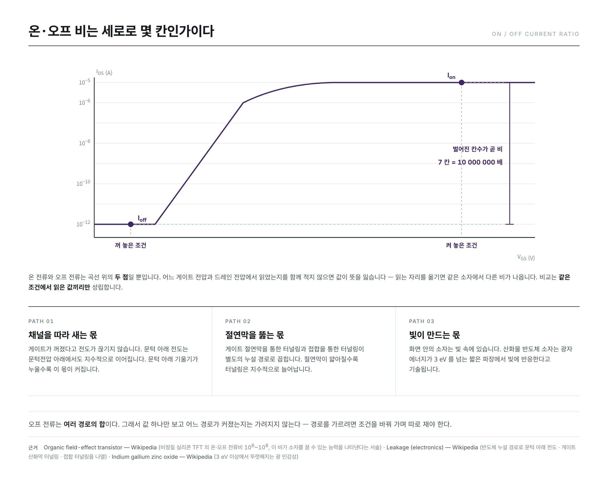
The principle seen in #03 applies here unchanged. All three are defined values. Unless it is settled where on the curve to read — at what gate voltage and at what drain voltage — the value is not settled either. So on current and off current keep their meaning only when written down together with the conditions of the reading.
The meaning of the ratio is intuitive. The Wikipedia "Organic field-effect transistor" article writes that the on/off current ratio is a value expressing the ability to turn the device off, and gives the value for the amorphous silicon thin-film transistor it compares against as 106~108. From a million-fold to a hundred-million-fold.
Once the logarithmic axis becomes familiar, this value can be read straight off by eye. How many divisions apart the two sit vertically is the difference in decades, and that difference is the ratio. Seven divisions apart is a factor of 107.
The relation between the two numbers also emerges here. The measurement paper by Bohuslavskyi and co-workers writes that a very small swing approaches an ideal switch and leads to a high on/off current ratio and low standby power. The smaller the swing, the narrower the voltage within which the same number of decades can be crossed, so the number of decades that can be opened up within a given voltage range grows.
In a pixel switch, the off current buys time
In #04 of the earlier series, a single pixel of a liquid crystal display was reduced to one switch and one capacitor. A gate line opens a row of switches and writes the brightness value in, and once the switch has been turned off, the charge held in the capacitor holds that value until the next turn.
What the off current does becomes clear here. Current leaking through a switch that has been turned off eats away at the stored charge. If enough leaks, the value blurs before the next turn comes round. The reason the off current must be small in a pixel switch is not speed or strength but how long it holds out.
How much this time changes with the material is written down in the open literature as well. The Wikipedia "Indium gallium zinc oxide" article writes that this oxide semiconductor has a very low leakage current, and that as a result it retains the screen information without rewriting it, bringing power consumption down to between a fifth and a tenth of the conventional level. Reducing how much leaks away is the same thing as reducing how often the value has to be written again.
Off current does not arrive by a single path
One last thing has to be made clear. Off current is a single name, but the paths that build up its value are several.
The Wikipedia "Leakage (electronics)" article lists the leakage paths in semiconductors side by side as follows.
- Quantum tunnelling through insulating regions — it grows exponentially as the thickness shrinks.
- Subthreshold conduction between the source and the drain of a MOSFET — the very region seen above.
- Gate oxide tunnelling across the gate insulator
- Junction tunnelling across heavily doped PN junctions
- Leakage between interconnects
To this, light is added. A device inside a display is always sitting in light. The Wikipedia "Indium gallium zinc oxide" article writes that these devices have some photosensitivity and that the effect becomes pronounced above a photon energy of 3 eV — that is, from deep violet into the ultraviolet.
So the value of the off current alone does not reveal which path has grown. Separating the paths means measuring while varying temperature, drain voltage and lighting conditions one at a time. That method lies beyond the scope of this series, so it will be treated separately in another one.
Summary
- Subthreshold swing is the gate voltage it takes to raise the current tenfold. Its unit is mV/decade and, being the reciprocal of the slope, the smaller it is the steeper the curve.
- At room temperature there is a floor that cannot be crossed. 0.02585 V × 2.3026 = 0.0595 V, that is, about 60 mV/decade. What fixes this floor is not structure but temperature, and since it comes out of the thermal distribution of the carriers it is called the Boltzmann limit.
- The actual value is the lower bound multiplied by m = (Cox + Cit)/Cox. The gate voltage divides into the surface potential and the insulator's share, and when charge trapped at the interface takes more of that share, less voltage reaches the channel and the curve reclines.
- On current, off current and their ratio are all defined values for which the conditions of the reading are part of the value. On a logarithmic axis the ratio reads directly as the number of divisions opened up vertically. For amorphous silicon thin-film transistors an on/off ratio of 106~108 is quoted.
- The reason the off current must be small in a liquid crystal pixel switch is that the stored charge has to survive until the next turn. That off current is the overlapped sum of subthreshold conduction, insulator tunnelling, junction tunnelling and light-induced current.
So far, threshold voltage and subthreshold slope have shown us where the device turns on and the shape of the turning-on. The next installment moves on to the story after it is on, looking at how mobility — the measure of how well the carriers in the channel move — is drawn out of the transfer curve.
References
- Subthreshold slope — Wikipedia : the log-linear behaviour of the subthreshold region, the definition of a decade as a tenfold increase in drain current, S = ln(10)(kT/q)(1 + Cd/Cox) and its minimum ln(10)kT/q (60 mV/dec at 300 K), and the room-temperature measurement of about 70 mV/dec for scaled devices
- Subthreshold conduction — Wikipedia : the definition that current continues to flow between source and drain even below the threshold voltage, and the statement that its log-linear slope is used as a measure of switching efficiency
- Thermal voltage — Wikipedia : the definition VT = kT/q and about 25.85 mV at 300 K
- Tunnel field-effect transistor — Wikipedia : the statement that the thermal Maxwell–Boltzmann tail of the carriers limits the subthreshold swing to about 60 mV/decade at room temperature, and the description of this as a fundamental limit on power scaling
- A. Beckers, F. Jazaeri, C. Enz, "Revised theoretical limit of subthreshold swing in field-effect transistors" — arXiv:1811.09146 : names this lower bound the Boltzmann limit and reports a temperature-dependent limit departing from it at cryogenic temperatures
- H. Bohuslavskyi et al., "Cryogenic Subthreshold Swing Saturation in FD-SOI MOSFETs described with Band Broadening" — arXiv:1903.05409 : the definitions S = m·ln10·kT/e and m = (Cox + Cit)/Cox ≥ 1, the relation by which the gate voltage divides into the surface potential and the insulator's share, the measured m = 1.14 and 1.23, 7.3 mV/dec at 4.3 K, and the statement that a small swing leads to a high on/off ratio
- Organic field-effect transistor — Wikipedia : the statement that the on/off current ratio expresses the ability to turn the device off, and the 106~108 of amorphous silicon TFTs
- Leakage (electronics) — Wikipedia : the list of leakage paths in semiconductors — quantum tunnelling through insulating regions, subthreshold conduction, gate oxide tunnelling, tunnelling across heavily doped PN junctions, and leakage between interconnects
- Indium gallium zinc oxide — Wikipedia : the very low leakage current, the statement that screen information is retained without rewriting so that power consumption falls to a fifth or a tenth, and the photosensitivity that becomes pronounced above a photon energy of 3 eV
- ※ The portions quoted from Wikipedia articles in the list above are licensed under CC BY-SA 4.0.