Over the previous three installments we learned how to read the curves. The output curve showed what the drain voltage does, and the transfer curve what the gate voltage does. In the last installment we confirmed that the numbers extracted from those curves are defined values — that without writing down the method and the conditions, no comparison is possible.
This installment goes one step further in. We look at how to write down, as numbers, the point at which a device turns on and how sensitively it responds. The first is the threshold voltage Vth, the second the transconductance gm. The order is reversed, and gm is set up first, because one of the methods for extracting the threshold voltage uses gm as its tool.
There is one question to answer: how to write "it turns on" and "it responds well" as numbers that mean the same thing to everyone who reads them.
The operating values in this text are examples chosen to show the calculation, not the specifications of any particular company. Every figure quoted has been verified in the public literature, and the sources are listed at the end.
Transconductance — the slope of the transfer curve
The English Wikipedia article "Transconductance" defines transconductance as the electrical characteristic relating the current through the output of a device to the voltage across the input, and writes the expression as follows.
gm = ΔIout / ΔVin
Carried over to a transistor, the input is the gate voltage and the output the drain current.
gm = ∂IDS / ∂VGS
The numerator is the change in drain current, the denominator the change in gate voltage. A paper on threshold voltage extraction for zinc oxide thin-film transistors (DOI 10.3390/ma16082940) writes the same expression.
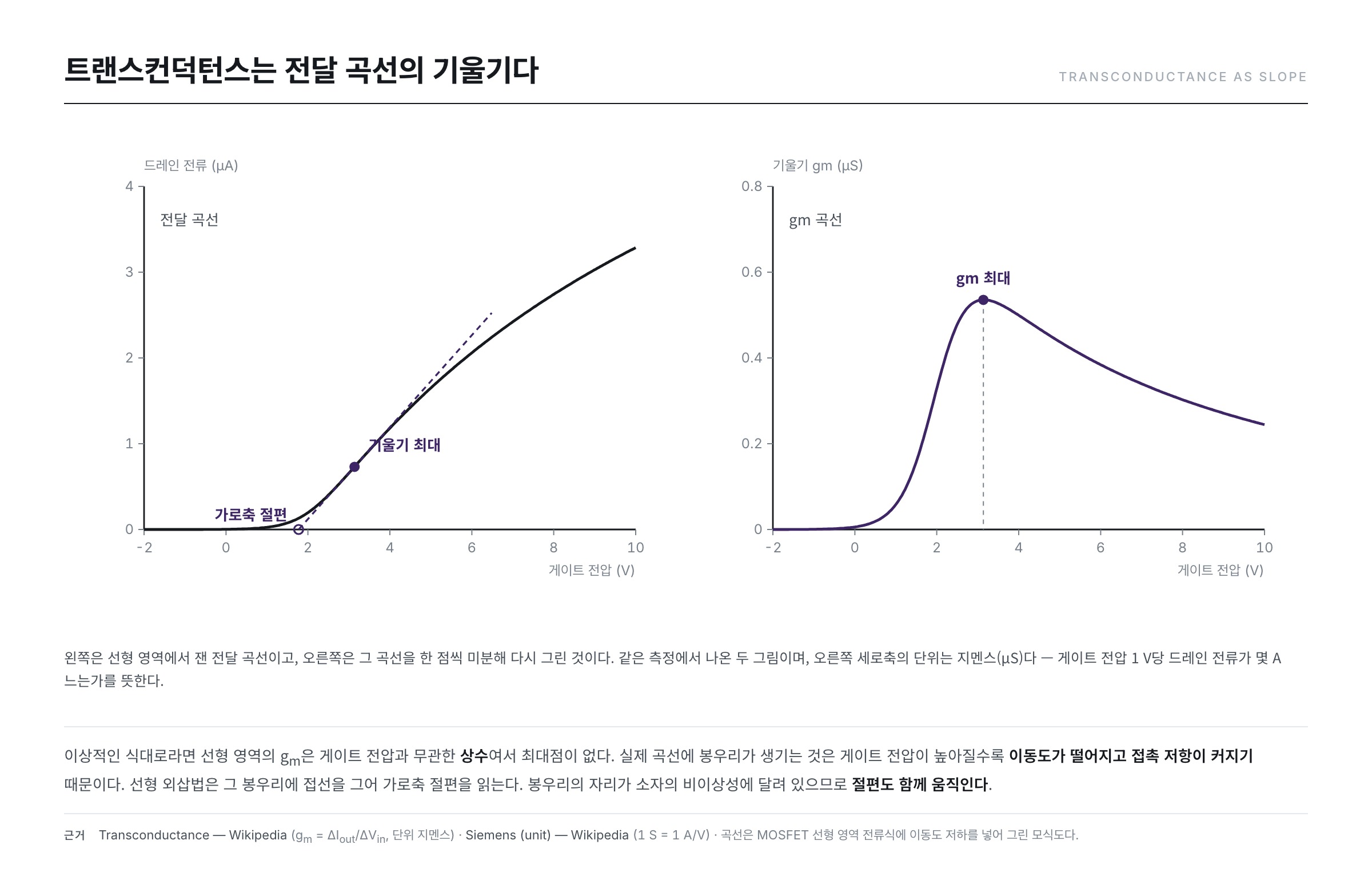
The transfer curve of installment #02 had gate voltage on the horizontal axis and drain current on the vertical. So gm is not a new physical quantity but the slope of that curve. Follow the curve point by point, measure the slope and plot it again, and you have the gm curve.
The unit tells you the meaning
The unit of gm is the siemens (symbol S). The Wikipedia article "Siemens (unit)" states that 1 siemens is the reciprocal of 1 ohm and equals amperes divided by volts, and unfolds the meaning this way — a device whose conductance is 1 siemens passes 1 ampere more current for every 1 volt of additional potential difference.
Carried over to a transistor, the meaning of gm follows immediately. A large gm means that a small movement of the gate voltage moves the drain current a great deal — the ability to turn a change at the input into a change at the output.
The "Transconductance" article notes that the subscript m comes from mutual. The name was attached because the input and the output lie at different terminals, and the notation distinguishes it from ordinary conductance, which looks at the ratio of voltage to current at a single terminal.
Its uses split in two. Used as an amplifier, gm is the source of the gain — the ratio by which a small wobble in input voltage turns into a large wobble in output current is precisely gm. Used as a switch, the same value governs the vigour of turning on. How far the gate voltage must be pushed to reach the target current is set by gm.
Change the region and the equation changes too
If gm is a slope, then differentiating the current equation gives the equation for gm. But as we saw in installment #01, the equation for the drain current differs from region to region. We take the two equations carried in the Wikipedia article "MOSFET" just as they stand.
The linear region
The condition is VGS > Vth together with VDS < (VGS − Vth).
ID = μ Cox (W/L) [ (VGS − Vth) VDS − VDS2 / 2 ]
Unpacking the symbols: μ is the carrier mobility, Cox the capacitance per unit area of the gate insulator, W the width of the channel and L its length. W/L is that ratio from the dimensional normalization seen in installment #03.
Differentiate with respect to VGS. Inside the bracket only the first term contains VGS, and it is first order.
gm,lin = μ Cox (W/L) VDS
There is no VGS in the result. By this equation the gm of the linear region is a constant independent of the gate voltage, and is instead proportional to VDS.
The saturation region
The condition is VGS > Vth together with VDS ≥ (VGS − Vth). The "MOSFET" article calls this point pinch-off and explains it as the state in which the channel has disappeared at the drain end.
ID = ( μ Cox / 2 ) (W/L) (VGS − Vth)2 ( 1 + λ VDS )
λ is the term carrying channel length modulation. Leave it out (λ = 0) and differentiate. Differentiating the square brings the exponent 2 out in front, where it cancels the division by 2.
gm,sat = μ Cox (W/L) (VGS − Vth)
This time VGS remains. The gm of the saturation region grows in proportion to the gate voltage. What was a constant in the linear region becomes a straight line here. Without stating in which region the value was measured, even a single gm cannot be compared.
(VGS − Vth) is called the overdrive voltage VOV, that is, the amount by which the threshold has been exceeded. Dividing the saturation current equation by gm,sat gives the following.
gm,sat = 2 ID / VOV
The expression obtained by differentiation agrees with the one in the Wikipedia article "Transconductance."
Once through in numbers
This article assumes the following for its calculation: mobility μ = 10 cm2/V·s, a gate insulator of silicon dioxide 100 nm thick, and W/L = 20.
We start with Cox. The Wikipedia article "Relative permittivity" gives the relative permittivity of silicon dioxide as 3.9, and the article "Vacuum permittivity" gives the vacuum permittivity as 8.8541878188 × 10⁻¹² F/m (= 8.854 × 10⁻¹⁴ F/cm). We put these into the parallel-plate capacitance C = ε / d.
Cox = 3.9 × 8.854 × 10−14 ÷ (100 × 10−7 cm) = 3.45 × 10⁻⁸ F/cm2
Let us gather the front part into a single lump. μ Cox (W/L) = 10 × 3.45 × 10−8 × 20 = 6.9 × 10⁻⁶ A/V2.
- Measured in the linear region at VDS = 0.1 V, gm,lin = 6.9 × 10−6 × 0.1 = 0.69 μS.
- In the saturation region with VOV = 5 V, gm,sat = 6.9 × 10−6 × 5 = 34.5 μS.
The same device, and a factor of 50 between them. The check agrees as well: ID = ½ × 6.9 × 10−6 × 52 = 86.3 μA, and 2 ID / VOV = 34.5 μA/V, the same as above. 34.5 μS means that raising the gate voltage by 1 V increases the drain current by 34.5 μA.
Three ways of extracting the threshold voltage
Now for the point of turning on. The Wikipedia article "Threshold voltage" defines the threshold voltage as the minimum gate-source voltage that creates a conducting path between source and drain.
The definition is one line; the measuring is not. The "Threshold voltage" article states the reason — leakage current flows even below the threshold, so there is no true on-off transition. Nowhere on the curve is there a mark saying "from here a conducting path has formed." So people set a rule and point at one spot.
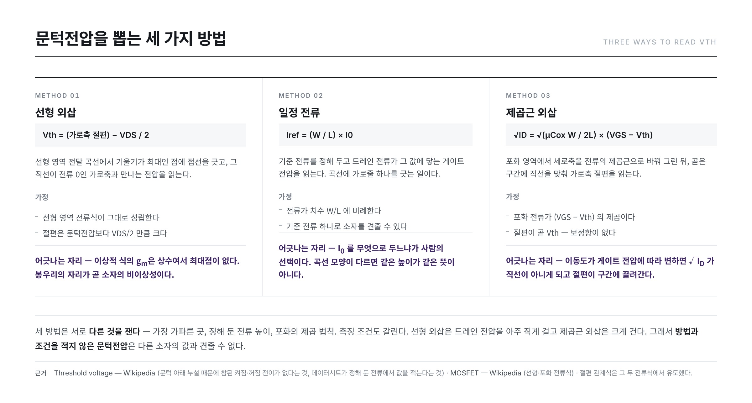
① Linear extrapolation
How it is done. Draw the transfer curve in the linear region and lay a tangent at the point where gm is greatest. Read the gate voltage at which that straight line meets the horizontal axis at 0 current.
What it assumes. That the linear-region equation above holds as it stands. Arranged as a function of VGS that equation is a straight line, and the point at which the current becomes 0 is VGS = Vth + VDS/2. The intercept comes out larger than the threshold voltage by VDS/2, so that much must be subtracted from the value read. Here lies the reason for applying a very small drain voltage — it shrinks the quantity to be corrected in the first place.
Where it goes astray. In the differentiation just performed, the gm of the linear region was a constant, and a constant has no maximum. That a peak appears on a real curve at all is itself a sign that this equation does not hold as it stands. As the gate voltage rises, the mobility falls and the contact resistance grows, the slope turns back down, and a peak is formed. Since the location of the peak rests on the non-idealities of the device, the intercept moves with it. A paper on the problem of the gate voltage also modulating the contact resistance (arXiv:2404.19022) reports that extraction methods that leave this effect out can overestimate the mobility by more than a factor of 2.
The zinc oxide paper cited earlier shows this in numbers. Extracting from the same device by linear fitting, but taking the fitting range up to 40 V, gives 25 V, while extending it to 60 V and 80 V raised it to 36 V and 42 V. The device was untouched; only the stretch on which the ruler was laid was changed.
② Constant current
How it is done. Fix a reference current and take as the threshold voltage the gate voltage at which the drain current reaches that value. It is the point where a horizontal line drawn across the curve meets it.
The Wikipedia article "Threshold voltage" describes this practice as well: datasheets fix a measurable current value and quote the threshold voltage as the voltage at that current. The values it gives as examples are 250 μA and 1 mA.
What it assumes. That several devices can be compared against a single reference current. But W/L enters the current equation as a factor, so a device twice as wide passes twice the current at the same gate voltage. Use one absolute value for every set of dimensions and the wider device reaches that line first, giving a lower threshold voltage. That is why the reference current is written in the form Iref = (W/L) × I0.
Where it goes astray. What to set I0 to is a human choice. Cut a device with a gentle subthreshold slope and one with a steep slope along the same horizontal line, and shifting the height of that line even slightly changes the difference between the two values. When the shapes of the curves differ, one line height does not mean the same thing for both devices.
In exchange its merit is plain. It needs neither differentiation nor a tangent, and is read straight off a single curve.
③ Square-root extrapolation
How it is done. Measure the transfer curve in the saturation region and replot it with the vertical axis changed to the square root of the current. Fit a straight line to the straight stretch of that graph and read the point where it meets the horizontal axis.
What it assumes. That the saturation current equation depends on (VGS − Vth) as a square. Take the square root of both sides.
√ID = √( μ Cox W / 2L ) × (VGS − Vth)
The right-hand side is first order in VGS. The point at which √ID becomes 0 is exactly VGS = Vth. Unlike linear extrapolation, there is no correction term to subtract. The mobility falls out of the slope as well, so a single extrapolation yields two parameters.
Where it goes astray. The square law is the premise. If the mobility varies with gate voltage, √ID becomes a gentle curve rather than a straight line. The moment a ruler is laid on a curve, the problem of ① returns — the intercept changes according to which stretch is fitted.
The three methods do not give the same answer
The three methods measure different things.
- Linear extrapolation — the place where the slope is steepest. A property of the stretch that is already well turned on.
- Constant current — a fixed current height. One point partway through turning on.
- Square-root extrapolation — the square law of the saturation region. A property of the state in which a large drain voltage is applied.
Different criteria, different answers. The conditions differ too — linear extrapolation applies a very small drain voltage while square-root extrapolation applies a large one. As we saw in installment #03, the drain voltage changes the shape of the curve itself.
And so the question "what is the threshold voltage of this device" has no single settled answer. It becomes an answer only with the method and conditions attached, as in "the value obtained by linear extrapolation in the linear region at VDS = 0.1 V." Holding up two threshold voltages that do not state this is comparing lengths measured with different rulers. It is not that the values are wrong; the comparison does not hold.
The threshold voltage is not a constant engraved in the device
Even with the method fixed, the value does not sit still.
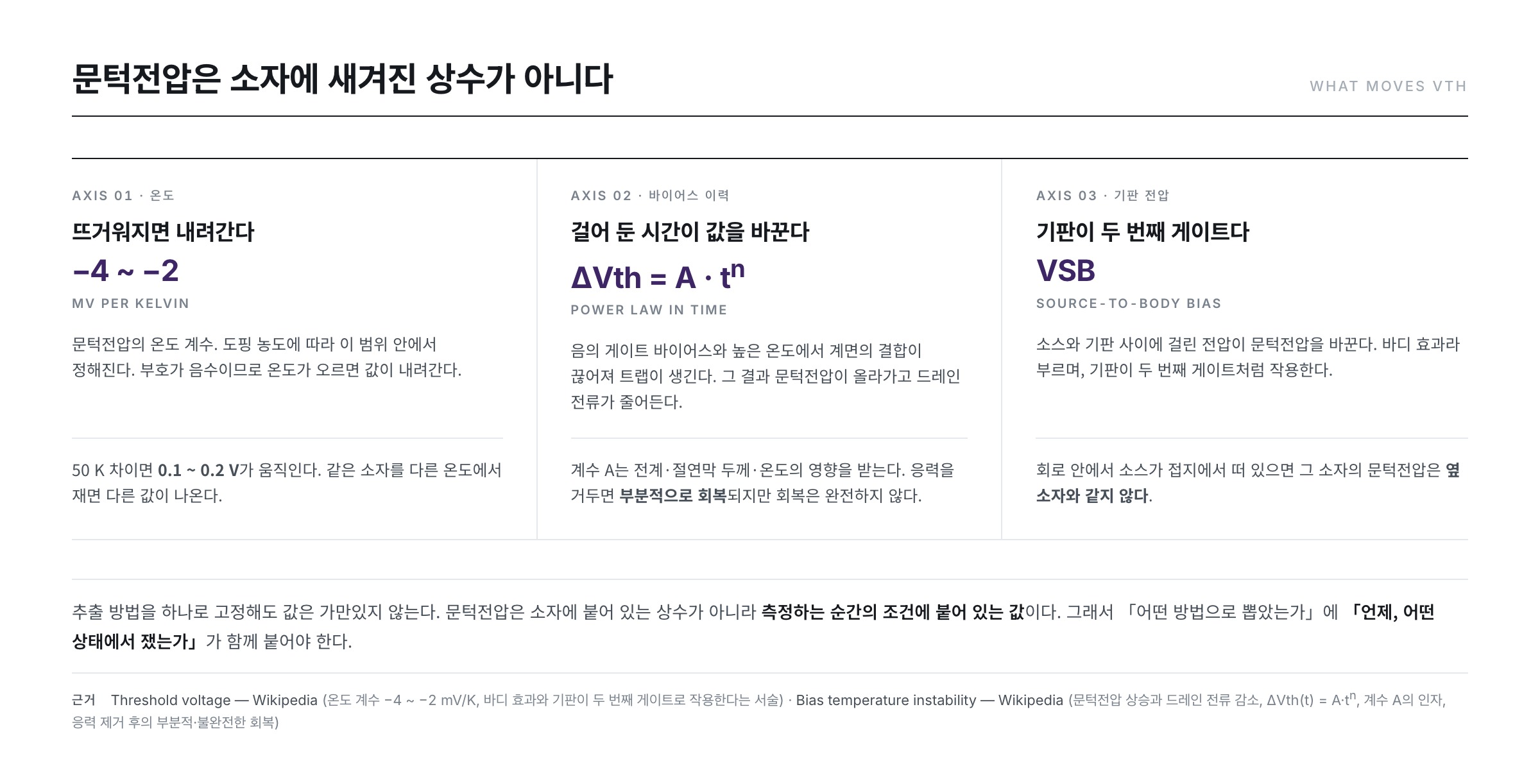
Temperature. The Wikipedia article "Threshold voltage" gives the temperature variation of the threshold voltage as between −4 mV/K and −2 mV/K, depending on the doping concentration. The sign is negative, so it falls as things get hotter. A difference of 50 K moves it by 0.1 V to 0.2 V.
Bias history. Holding a voltage on the gate for a long time changes the device in itself. The Wikipedia article "Bias temperature instability" describes how, under negative gate bias and high temperature, bonds at the interface break and traps are created, with the result that the threshold voltage rises and the drain current falls. The amount of the shift is approximated in the form ΔVth(t) = A · tn, and the coefficient A is affected by the electric field, the insulator thickness and the temperature. It adds that on removing the stress there is partial recovery, though the recovery is not complete.
Substrate voltage. The "Threshold voltage" article carries the body effect, by which the voltage between source and substrate changes the threshold voltage, and explains that the substrate acts like a second gate. If the source floats off ground inside a circuit, that device's threshold voltage is not the same as its neighbour's.
Light moves the threshold voltage too, but that is a story of materials and defects and lies beyond the scope of this series. It will be taken up in another one.
The threshold voltage is a value attached to the conditions at the moment of measurement. To "state the method" is added one more thing: "when and in what state it was measured."
Summary
- gm = ∂IDS/∂VGS is the slope of the transfer curve, and its unit, the siemens, means "how many A the current rises for every 1 V."
- The gm of the linear region is independent of the gate voltage, while the gm of the saturation region is proportional to the gate voltage. Under the example conditions they were 0.69 μS and 34.5 μS, a factor of 50 apart.
- Linear extrapolation, constant current and square-root extrapolation use different criteria. Linear extrapolation requires subtracting VDS/2 from the intercept, whereas for square-root extrapolation the intercept is Vth itself.
- And so the answers differ from one another. There is a report in which changing only the stretch the ruler was laid on gave 25, 36 and 42 V. A threshold voltage without its method and conditions written down cannot be an object of comparison.
- Nor is the threshold voltage a fixed property. It moves with temperature, bias history and substrate voltage, and the recovery is not complete either.
The next installment looks at how the mobility contained in that slope is drawn out, and why that value is not a constant of the material.
References
- Transconductance — Wikipedia : the definition of transconductance and gm = ΔIout/ΔVin, the unit being the siemens, the subscript m coming from mutual, and the MOSFET relation gm = 2ID/VOV
- Siemens (unit) — Wikipedia : 1 siemens = the reciprocal of 1 ohm = A/V, and the reading that for every 1 V more there is 1 A more
- MOSFET — Wikipedia : the drain-current equations for the linear and saturation regions with the conditions under which they hold, and pinch-off
- Threshold voltage — Wikipedia : the definition of the threshold voltage, the absence of a true on-off transition because of subthreshold leakage, the practice by which datasheets quote the value at a fixed current (250 μA, 1 mA), the temperature coefficient of −4 ~ −2 mV/K, and the body effect
- Bias temperature instability — Wikipedia : the rise of the threshold voltage and fall of the drain current, ΔVth(t) = A·tn, and the partial, incomplete recovery after the stress is removed
- Relative permittivity — Wikipedia : the relative permittivity of silicon dioxide, 3.9
- Vacuum permittivity — Wikipedia : the vacuum permittivity, 8.8541878188 × 10⁻¹² F/m
- Threshold-Voltage Extraction Methods for Disordered ZnO Thin-Film Transistors, Materials 16, 2940 (2023) : the definition gm = ∂Ids/∂Vgs, the account that several methods such as linear fitting and constant current are in use, and the measurement in which changing the fitting range to 40, 60 and 80 V changed the value to 25, 36 and 42 V
- Mobility and Threshold Voltage Extraction in Transistors with Gate-Voltage-Dependent Contact Resistance (arXiv:2404.19022) : the finding that when the gate field also modulates the contact resistance, existing extraction methods can overestimate the mobility by more than a factor of 2
- ※ Passages quoted from the Wikipedia articles in the list above are under the CC BY-SA 4.0 license.