The previous post organised the shared concepts of etching. This one is about dry etching — removing material with nothing but the reactive species of a plasma, no liquid involved. Where fine patterns and near-vertical sidewalls are required, there is no alternative.
Not cutting, but "converting to gas and pumping it out"
The principle of dry etching is not physical scraping. The heart of it is volatility.
The plasma dissociates the process gas into highly reactive atoms and radicals. When these meet the material at the substrate surface and react, the product becomes a volatile species. Once it is a gas, the vacuum pump simply removes it. Dry etching is therefore turning a solid into a gas and exhausting it.
Why does that matter? Because a material whose products do not volatilise cannot be etched this way. If the reaction product does not become a gas, it piles up on the surface as residue and actually blocks the etch. So each material has its own set of usable gases. "Which gas do we use" is not a preference — it is a question decided by the boiling point of the reaction product.
| Reaction product | Melting point | Boiling (or sublimation) point | Dry etch feasibility |
|---|---|---|---|
| SiF₄ (Si + fluorine) | −95.0℃ | −90.3℃ | ideal — gaseous at room temperature |
| SiCl₄ (Si + chlorine) | −68.7℃ | 57.7℃ | good — evaporates readily |
| MoF₆ (Mo + fluorine) | 17.5℃ | 34.0℃ | good — gaseous with slight heating |
| AlCl₃ (Al + chlorine) | 180℃ (sublimes) | — | workable with a heated substrate |
| AlF₃ (Al + fluorine) | 1,290℃ (sublimes) | — | no — accumulates and blocks the etch |
| CuCl (Cu + chlorine) | 423℃ | 1,490℃ | no — effectively impossible |
The values are published properties of each compound (Silicon tetrafluoride, Aluminium chloride, Aluminium fluoride, Copper(I) chloride). Put rows four and five side by side and why fluorine chemistry is never used on aluminium is obvious at a glance — the same metal, only the partner element changed, and the sublimation point differs by 1,110℃.
Neither chemistry alone nor physics alone
It is common to say dry etching is "chemical reaction plus ion bombardment", but rarely explained why the two must go together. A famous experiment of 1979 answered that.
The experiment was simple. Expose a silicon surface to a fluorine-bearing gas alone; then to an argon ion beam alone; finally to both at once. In the first two cases the etch rate was negligible, but the moment both were applied together the rate jumped by more than an order of magnitude — far more than the simple sum of the two (J. W. Coburn, H. F. Winters, J. Appl. Phys. 50(5), 3189 (1979)).
The explanation runs like this. With chemistry alone a reacted layer does form, but nothing removes it; with ions alone the sputter yield is so low that almost nothing is cut. When ions shake the bonds loose, the chemical reaction at that spot accelerates sharply, and the weakened layer is then easily knocked off by further ion impact. The ion is not the cutting tool but the key that opens the reaction.
This synergy explains the anisotropy of dry etching. Ions arrive vertically, so the synergy happens only at the bottom; the sidewalls, reached only by neutral species, are barely etched. Directionality does not come from ions "hitting harder" — it comes from the reaction being fast only where the ions land.
Three generations — PE, RIE and high-density plasma
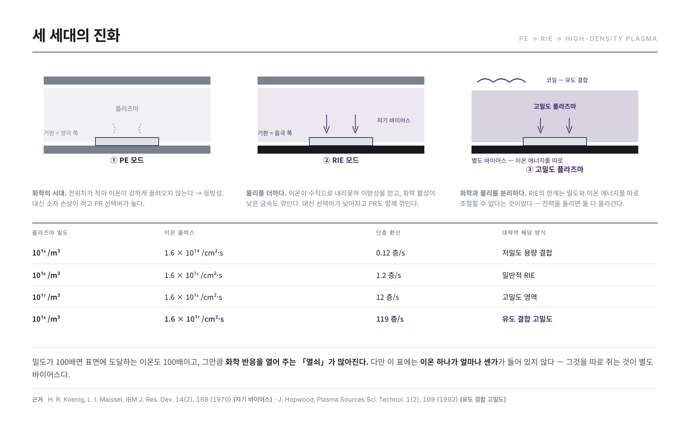
1. PE mode — the age of chemistry
The early approach. A plasma is struck between two parallel plate electrodes and the substrate is placed on the anode side. In this arrangement the potential difference between substrate and plasma is small, so ions are not strongly drawn in.
The etch therefore proceeds mostly by chemical reaction. Chemistry has no preferred direction, so the result is isotropic and undercuts the PR. The advantages are clear in exchange — little device damage and high selectivity to PR. It runs at relatively high pressure and suits silicon and nitride families.
2. RIE mode — adding physics
As the demands grew — etch metals, faster, more vertically — the arrangement changed: the substrate moved to the cathode side. Because of the self-bias seen in post 9, a large potential difference forms at the cathode and positive ions are strongly accelerated toward the substrate.
Why self-bias arises was worked out in 1970. When an RF electrode is coupled through a capacitor, electrons — far lighter than ions — reach the electrode much more often during a half cycle. Negative charge therefore accumulates, and the ratio of electrode areas decides which side carries the larger potential: the smaller electrode develops the larger negative bias (H. R. Koenig, L. I. Maissel, IBM J. Res. Dev. 14(2), 168 (1970)). Putting the substrate on the small electrode is essentially the definition of RIE.
Now the etch is not chemistry alone. The physical impact of ions striking the surface is added, and two things change.
- Anisotropy — ions drive straight down, so the bottom is cut and the sidewall less so. A near-vertical profile results.
- Chemically inert materials become etchable — metal etching, hard by chemistry alone, becomes possible.
There is a price. Hard-hitting ions mean lower selectivity and more damage, and the PR is consumed along with everything else.
3. High-density plasma — separating chemistry from physics
The fundamental limitation of RIE was that plasma density and ion energy cannot be adjusted separately. Raise the power and both rise together.
The answer was to separate where the plasma is made from where the ions are pulled. RF is driven through a coil above the chamber to generate a high-density plasma by inductive coupling, while a separate bias on the substrate sets ion energy independently. Producing such a plasma over a large area with a planar coil is captured in patent form (US 4,948,458).
Wikipedia describes the structure precisely — "ICP is used as a high density source of ions which increases the etch rate, whereas a separate RF bias is applied to the substrate to create directional electric fields near the substrate to achieve more anisotropic etch profiles" (Reactive-ion etching). The quantitative characteristics of inductively coupled plasmas were organised in a 1992 review, whose central point is that densities two orders of magnitude above capacitive coupling are obtainable at low pressure (J. Hopwood, Plasma Sources Sci. Technol. 1(2), 109 (1992)).
What "two orders of magnitude" actually means becomes clear on calculation. The ion flux entering the sheath edge is roughly density times the Bohm velocity, and for argon at an electron temperature of 3eV the Bohm velocity is about 2,690 m/s. Divide by the areal density of a monolayer of silicon atoms (about 1.36 × 10¹⁵ per cm²) to express it as "how many monolayers' worth of ions arrive per second":
| Plasma density | Ion flux | In monolayers | Roughly which scheme |
|---|---|---|---|
| 10¹⁵ /m³ | 1.6 × 10¹⁴ /cm²·s | 0.12 layers/s | low-density capacitive |
| 10¹⁶ /m³ | 1.6 × 10¹⁵ /cm²·s | 1.2 layers/s | ordinary RIE |
| 10¹⁷ /m³ | 1.6 × 10¹⁶ /cm²·s | 12 layers/s | high-density regime |
| 10¹⁸ /m³ | 1.6 × 10¹⁷ /cm²·s | 119 layers/s | inductively coupled, high density |
The table was computed directly from the Bohm flux expression. A hundredfold density is a hundredfold ion arrival rate, hence that many more "keys" opening chemical reactions. Note what the table does not contain: how energetic each ion is — that is the value set by the separate bias. The essence of high-density plasma is splitting "how many" and "how hard" into two independent knobs.
Pressure decides direction
Why dry etchers insist on running at low pressure is also a matter of calculation. Ions accelerate across the sheath toward the substrate, and any collision with a neutral gas molecule on the way deflects them. The distance they can travel without a collision is the mean free path.
λ = kT / (√2 · π · d² · P) — d: molecular diameter, P: pressure, T: temperature
With a molecular diameter of 0.37nm at room temperature, varying only the pressure:
| Pressure | Mean free path | Compared with a sheath of a few mm |
|---|---|---|
| 5 mTorr | 10.2 mm | crosses without collision — excellent directionality |
| 10 mTorr | 5.1 mm | almost collisionless |
| 50 mTorr | 1.0 mm | a few collisions |
| 100 mTorr | 0.51 mm | many collisions — angular spread |
| 1 Torr | 0.051 mm | fully scattered — directionality lost |
The values were computed directly from the formula. Taking the sheath to be a few millimetres thick, ions begin colliding several times on the way across as soon as pressure exceeds a few tens of mTorr. A scattered ion arrives obliquely rather than straight down, and therefore strikes the sidewall as well. That rising pressure broadens the ion angular distribution has been treated theoretically too (I. N. Devyatko, A. V. Fadeev, Plasma Physics Reports 43(8), 838 (2017)).
This connects straight back to the anisotropy A of the previous post. Lower the pressure and A rises; raise the pressure and A falls. But lowering pressure reduces gas density and thus the supply of reactive species, sacrificing etch rate. Keeping density up at low pressure was exactly the motivation for high-density plasma. The three generations have all moved in one direction: lower the pressure while holding the density.
The gas is the chemistry
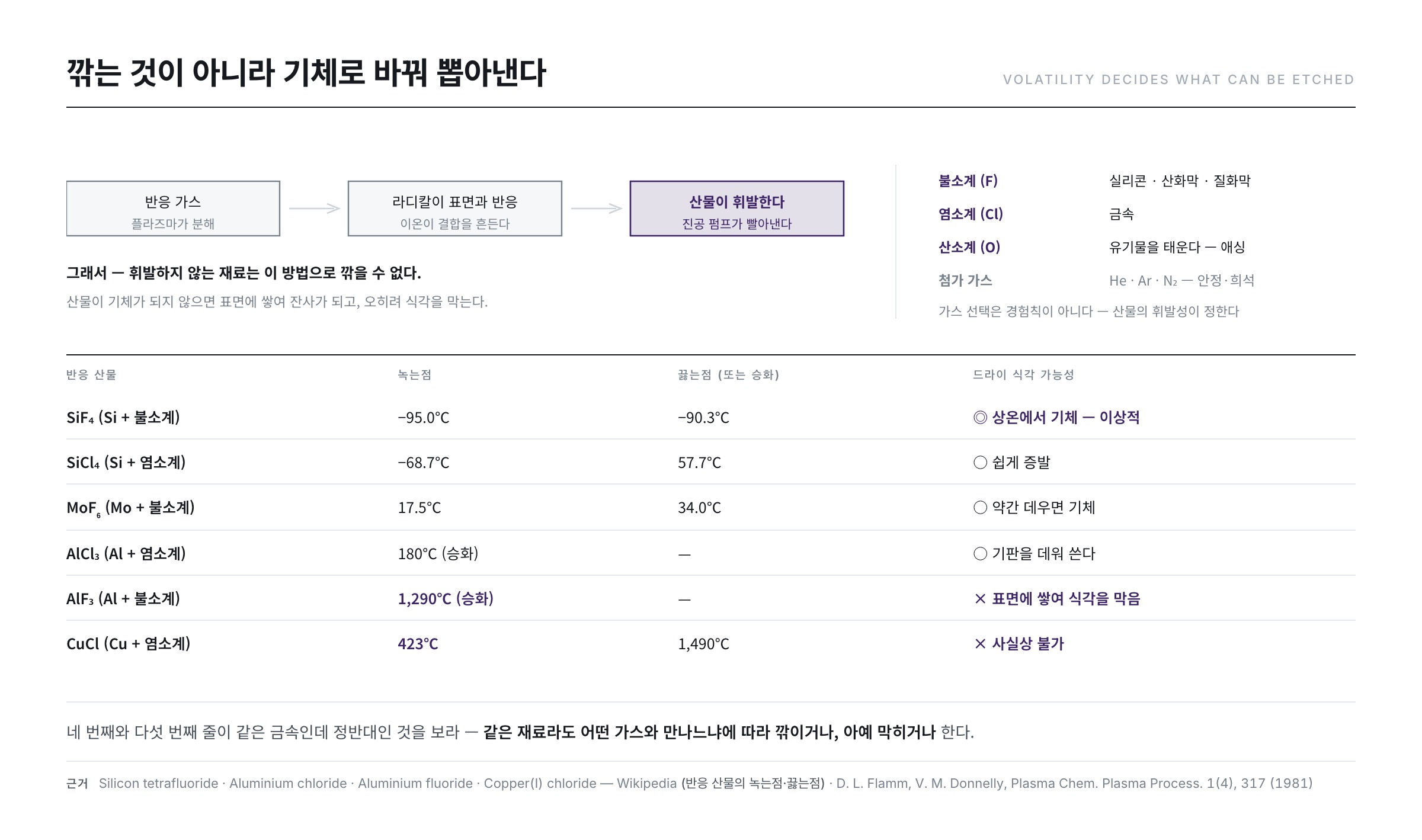
Which gas you use decides what you can etch.
- Fluorine family — CF₄, SF₆, CHF₃ and so on. Etches silicon, silicon oxide and nitride, because the product SiF₄ is highly volatile.
- Chlorine family — Cl₂, BCl₃, SiCl₄ and so on. Etches metals, because aluminium- and chromium-family chlorides are volatile.
- Oxygen family — O₂, O₃. Burns organics. The workhorse of resist removal (ashing), and also mixed into other gases to tune uniformity.
- Additive gases — He, Ar, N₂. Stabilise and spread the plasma, or dilute it to control etch rate.
What matters is that gas selection is not folklore. A classic 1981 review laid out how to design an etch gas along two axes: which radicals it produces and in what quantity, and whether the product those radicals form with the target material is volatile (D. L. Flamm, V. M. Donnelly, Plasma Chem. Plasma Process. 1(4), 317 (1981)). The volatility table above is the second axis; tuning radical ratios with additive gases is the first.
Standing the sidewall up — profile control
The real skill in etching shows in making the sidewall angle whatever you want. Three representative techniques.
Sidewall passivation — coating the sides
There is a limit to the anisotropy obtainable from ion synergy alone. So the gas is designed so that a thin protective film deposits only on the sidewalls. Adding a carbon-bearing gas or oxygen makes the reaction products stick to the surface as polymer or oxide; ions keep stripping it from the bottom, but the sidewalls, which ions do not reach, keep theirs. The result is a structure coated on the sides and cut only downward.
This mechanism has been modelled for oxygen-added fluorine high-density plasmas, where calculation and experiment show that oxygen flow changes sidewall oxide thickness and hence the profile (M. A. Blauw, E. van der Drift et al., J. Appl. Phys. 94(10), 6311 (2003)). Pushing the same idea to its extreme gives the scheme that alternates etch steps and passivation steps to produce very deep, very vertical structures (US 5,501,893).
Single-step etch — deliberately retreating the PR
Mixing in oxygen makes the PR recede faster than the metal. As the PR edge pulls back, the material beneath is exposed progressively, and the sidewall ends up as a gentle taper. Why would you want a slope? Because the dielectric to be deposited on top covers a vertical step poorly (the step coverage of post 11). The slope is created on purpose.
Two-step etch — start isotropic, finish anisotropic
First remove most of the film isotropically at high pressure to gain speed, then switch to low pressure and a different gas for an anisotropic etch that stands the sidewall up. Finally over-etch away the residue and close with endpoint detection. Recall the pressure table and the sequence makes sense — step one deliberately scatters the ions, step two deliberately stops the scattering. Gas species, ratio, pressure and bias power are the knobs of each step.
Ashing — burning it away with oxygen
The dry etch family has one more special use: ashing — burning the photoresist away with an oxygen plasma.
The principle is combustion. PR and other organics consist mostly of carbon, hydrogen and oxygen, so they react with oxygen radicals and leave as carbon dioxide and water. Wikipedia defines it as "a process of removing the photoresist from an etched wafer... converting it to CO, CO₂ and H₂O with an oxygen plasma" (Plasma ashing). The ashing rate is governed by the supply of oxygen radicals, and it has been quantitatively reported that changing discharge conditions to raise radical production directly changes the removal rate (R. Falkenstein, J. Appl. Phys. 83(10), 5095 (1998)).
There is a trap here. PR that has been through implantation or dry etching has a hardened surface: ion impact reorganises the carbon bonds into a kind of crust. A study that sectioned implanted resist after oxygen plasma ashing shows directly that this surface layer survives and is observed as residue (S. Yegnasubramanian, C. Draper, C. Pearce, MRS Proc. 265, 295 (1992)). That is why the strip process of post 17 uses chemistry and plasma together.
The shadow side — damage and static
Dry etching carries two hazards that wet etching does not.
First, plasma damage. High-energy ions striking the surface disorder the lattice, and ultraviolet light injects charge into dielectrics. In thin, sensitive layers such as the gate insulator, this damage translates directly into changed device characteristics.
Second, electrostatic discharge. Charge accumulates on the substrate inside the plasma, and if it discharges at once, wiring burns out. The larger the area the more charge can gather, so the risk grows. Hence the electrostatic chuck holding the substrate steadily, with helium flowed across its back to keep the substrate temperature from rising.
Temperature control is not incidental. Etch rate is exponentially sensitive to temperature, and the balance of deposition and removal of the sidewall passivation is set by temperature too. Since the gap between substrate back and chuck is vacuum, heat does not conduct across it; filling that narrow gap with helium provides a medium to hand the heat over.
Three common misconceptions
- "Dry etching cuts with ions." Sputtering alone would be far too slow for production and would have no selectivity. What actually removes the material is chemistry; the ion opens the reaction. The 1979 synergy experiment settled this.
- "More power means faster." In capacitive coupling, power raises density and ion energy together. Speed goes up, but selectivity falls and damage rises, so gains and losses have to be read together. High-density plasma exists precisely to split those two values apart.
- "The chamber is just a vessel." Films depositing on and flaking off the chamber walls change both the consumption and the supply of reactive species. That wall condition and sidewall passivation are entangled has been measured (M. Kogelschatz, G. Cunge, O. Joubert, Contrib. Plasma Phys. 44(5-6), 413 (2004)). Cleaning and seasoning are part of the recipe.
What the floor watches — three control points
- Plasma stability — applied power, reflected power, pressure, gas flow. If any one wobbles, etch rate and profile wobble with it.
- Chamber condition — polymer on the walls flakes off into particles, and the same recipe gives different results depending on chamber state. Hence clean steps between substrates and periodic seasoning.
- Damage indicators — threshold voltage and leakage current shifts measured right after etch give an indirect read on plasma damage.
In the next post (post 16) we go to the other side — wet etching. Why it is still used despite the weakness of a liquid spreading in all directions, what galvanic corrosion is when a multilayer metal stack is etched at once, and the chemistry of BOE that cleans the bottom of a narrow hole.
References
- J. W. Coburn, H. F. Winters, "Ion- and electron-assisted gas-surface chemistry — An important effect in plasma etching," J. Appl. Phys. 50(5), 3189 (1979) : the synergy experiment showing the combined etch rate far exceeds the sum of the parts
- H. R. Koenig, L. I. Maissel, "Application of RF Discharges to Sputtering," IBM J. Res. Dev. 14(2), 168 (1970) : electrode area ratio determining self-bias — the basis of the RIE configuration
- J. Hopwood, "Review of inductively coupled plasmas for plasma processing," Plasma Sources Sci. Technol. 1(2), 109 (1992) : density, electron temperature and low-pressure operation of inductively coupled plasmas
- D. L. Flamm, V. M. Donnelly, "The design of plasma etchants," Plasma Chem. Plasma Process. 1(4), 317 (1981) : a framework for designing etch gases from radical production and product volatility
- M. A. Blauw, E. van der Drift et al., "Modeling of fluorine-based high-density plasma etching of anisotropic silicon trenches with oxygen sidewall passivation," J. Appl. Phys. 94(10), 6311 (2003) : modelling how sidewall passivation thickness sets the profile
- I. N. Devyatko, A. V. Fadeev, "Effect of collisions on the angular distribution of ions under plasmachemical etching," Plasma Physics Reports 43(8), 838 (2017) : sheath collisions broadening the ion angular distribution — the basis of the pressure table
- R. Falkenstein, "Frequency dependence of photoresist ashing with dielectric barrier discharges in oxygen," J. Appl. Phys. 83(10), 5095 (1998) : quantitative measurement of how discharge conditions govern resist removal rate
- S. Yegnasubramanian, C. Draper, C. Pearce, "TEM investigation of implanted photoresist residues remaining after oxygen plasma ashing," MRS Proc. 265, 295 (1992) : cross-sections showing the hardened surface layer of implanted resist surviving as residue
- M. Kogelschatz, G. Cunge, O. Joubert, "Correlation and interaction between sidewall passivation and chamber walls deposition during silicon etching," Contrib. Plasma Phys. 44(5-6), 413 (2004) : measured entanglement of chamber wall state and sidewall passivation
- US 4,948,458 — Method and apparatus for producing magnetically-coupled planar plasma : generating an inductively coupled high-density plasma with a planar coil
- US 5,501,893 — Method of anisotropically etching silicon : alternating etch and passivation steps to build vertical structures
- Reactive-ion etching — Wikipedia · Plasma ashing — Wikipedia · Silicon tetrafluoride · Aluminium chloride · Aluminium fluoride · Copper(I) chloride : the ICP arrangement, the definition of ashing, and the melting and boiling points used in the volatility table