If dry etching is the precise one, why is wet etching still in use? The answer is simple — it is cheap, fast, and gentler on the underlying film. Most of the thick metal wiring of a backplane is cut this way. But handling liquid brings traps that dry etching does not have. This post is about those traps and how they are handled.
It cuts in every direction — the fate of isotropy
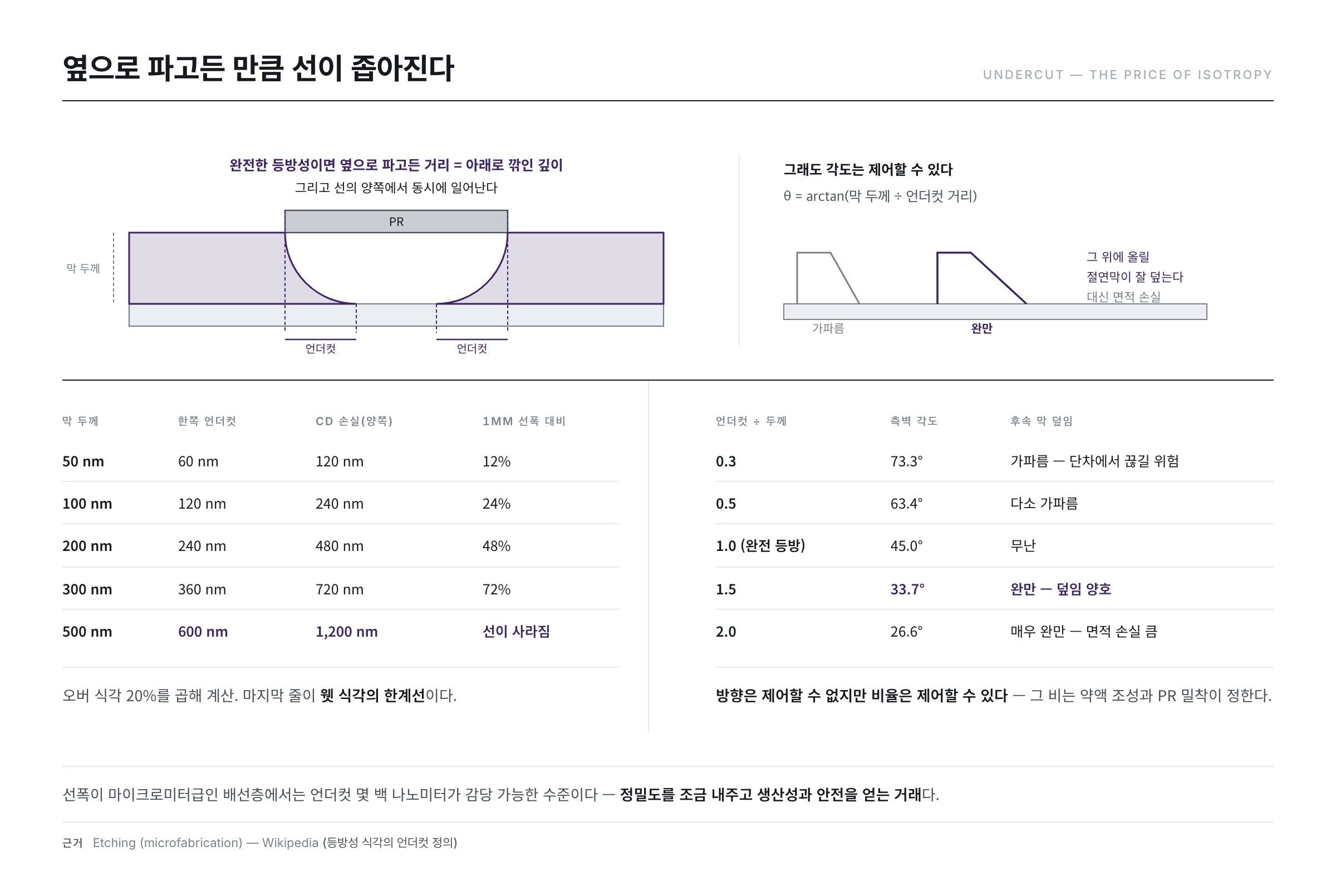
Liquid chemicals have no preferred direction. As much as they cut downward, they also cut sideways. The etchant therefore works its way beneath the area the PR covers, creating an undercut, and the finished line is narrower than designed. The CD bias of the previous post shows up here in force.
How much force needs no estimating. For a perfectly isotropic etch, the distance eaten sideways is exactly the depth cut downward. In the anisotropy definition of post 14 this is the case A = 0, and since it happens on both sides of a line, the CD loss is twice the film thickness. Add 20% over-etch and you get:
| Film thickness | Undercut per side | CD loss (both sides) | Against a 1μm line |
|---|---|---|---|
| 50 nm | 60 nm | 120 nm | 12% |
| 100 nm | 120 nm | 240 nm | 24% |
| 200 nm | 240 nm | 480 nm | 48% |
| 300 nm | 360 nm | 720 nm | 72% |
| 500 nm | 600 nm | 1,200 nm | the line disappears |
The table comes straight from the isotropic definition — undercut equals vertical depth — multiplied by 20% over-etch. The last row is the boundary of wet etching: try to leave a 1μm line while wet-etching a 500nm film and 1.2μm is eaten from the two sides, so the line itself vanishes. In other words, the minimum line width wet etching can produce is set by the film thickness, and that is why fine patterns cannot use it.
Even so, the reasons for using wet etching are clear.
- High selectivity — choose the chemistry and only a particular metal dissolves while the underlayer is barely touched.
- Almost no PR damage — with no ion bombardment, the mask survives intact.
- No plasma damage or static — the device suffers no electrical stress.
- High throughput and simple equipment — large substrates can be run continuously through the line.
On wiring layers with micrometre line widths, a few hundred nanometres of undercut is manageable. It is a trade: give away a little precision, gain throughput and safety.
The profile is not abandoned
Being isotropic does not mean the sidewall angle is beyond control, because the ratio of undercut distance to film thickness is the sidewall angle.
sidewall angle θ = arctan(film thickness ÷ undercut distance)
| Undercut ÷ thickness | Sidewall angle | Coverage by the next film |
|---|---|---|
| 0.3 | 73.3° | steep — risk of breaking at the step |
| 0.5 | 63.4° | somewhat steep |
| 1.0 (fully isotropic) | 45.0° | reasonable |
| 1.5 | 33.7° | gentle — good coverage |
| 2.0 | 26.6° | very gentle — large area penalty |
The table was computed directly from the formula. The sidewall angle of a wet etch is decided by how that ratio moves with the degree of peeling at the PR–metal boundary, which is tuned by the hard bake conditions of post 12 and by the etchant composition, especially oxidiser concentration. Raising the oxidiser concentration steepens the profile and lowering it flattens the profile — an inverse relationship that is well known.
Why would you want a gentle angle at all? Because of the step coverage of post 11. The dielectric to be laid on top covers a steep step poorly, so the lower rows of the table are actually favourable. In exchange, the flatter the angle the more area the wiring occupies — coverage traded against area.
When two metals meet, one is sacrificed — galvanic corrosion
Post 10 described wiring built as a three-layer sandwich. That structure causes an unexpected problem in wet etching.
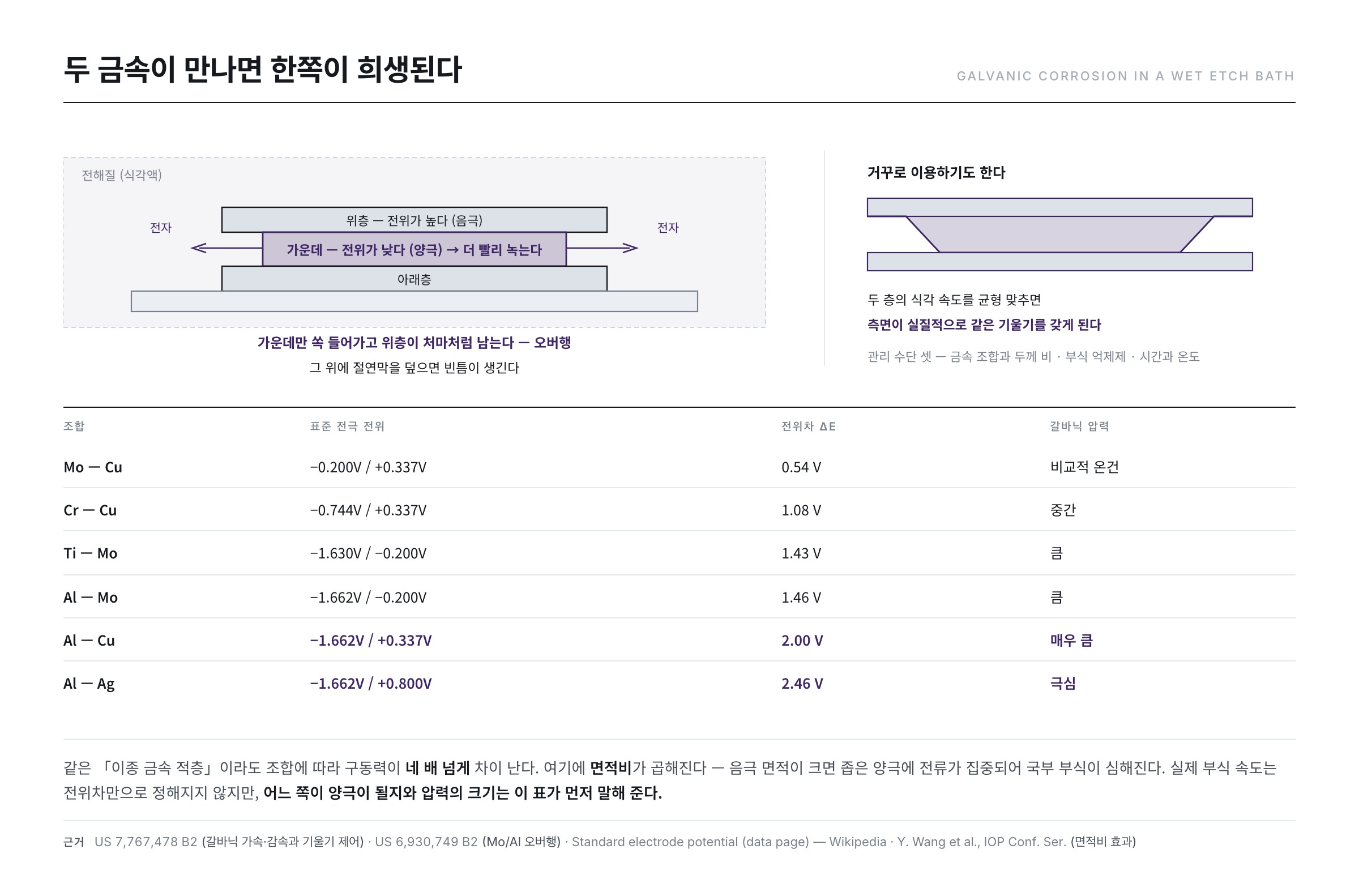
When different metals are electrically connected inside an electrolyte (the etchant), their potential difference drives electrons from one to the other. As a result the metal at lower potential becomes the anode and dissolves faster, while the metal at higher potential becomes the cathode and dissolves more slowly. This is galvanic corrosion (Galvanic corrosion).
Patent literature describes the phenomenon very clearly — "the etch rate of the cathodic metal becomes slower than when the metal is used alone. The etch rate of the anodic metal becomes faster than when used alone." A quantitative example is given as well: the electromotive forces of aluminium and copper being about −1.66V and +0.337V, aluminium acts as the anode and copper as the cathode in that pairing (US 7,767,478 B2).
How much this driving force differs between pairings can be compared using standard electrode potentials. The values below are taken from published standard electrode potential data and the differences computed (Standard electrode potential (data page)).
| Pairing | Standard electrode potentials | Difference ΔE | Galvanic pressure |
|---|---|---|---|
| Mo — Cu | −0.200V / +0.342V | 0.54 V | relatively mild |
| Cr — Cu | −0.744V / +0.342V | 1.09 V | moderate |
| Ti — Mo | −1.630V / −0.200V | 1.43 V | large |
| Al — Mo | −1.662V / −0.200V | 1.46 V | large |
| Al — Cu | −1.662V / +0.342V | 2.00 V | very large |
| Al — Ag | −1.662V / +0.800V | 2.46 V | extreme |
The table shows that the same phrase "dissimilar metal stack" hides a fourfold range in driving force. Actual corrosion rates in a real etchant are not set by potential alone — kinetics and surface state matter too — but which side becomes the anode, and how much pressure there is, is what this table tells you first.
On top of that comes the area ratio. If the cathode area exceeds the anode area, current concentrates on the narrow anode and local corrosion intensifies; this area-ratio effect has been confirmed experimentally (Y. Wang et al., IOP Conf. Ser. Mater. Sci. Eng. 322, 022046 (2018)). A thin middle layer sandwiched between broad upper and lower layers in a three-layer stack is precisely the case of "small anode, large cathode", which is why the defect is the middle layer receding on its own.
What does the defect look like in practice? Another patent puts it concretely — in a molybdenum/aluminium bilayer, "since aluminium has a higher etch rate than molybdenum, the potential difference from galvanic corrosion produces an overhang in the molybdenum layer on top of the aluminium" (US 6,930,749 B2). When the middle layer recedes and the upper layer remains as an eave, laying a dielectric on top leaves voids and the wiring reliability collapses.
Turned around — corrosion as a design tool
What is interesting is that the phenomenon is sometimes used in reverse. The same patent notes that "the etch rates of the aluminium layer and the copper layer can be balanced so that the side surfaces have substantially the same slope". In other words, adjusting the metal combination and thickness ratio produces the taper angle you want. The nuisance has been converted into a design variable.
There are three levers — designing the metal combination and thickness ratio, adding corrosion inhibitors to the etchant, and controlling etch time and temperature.
Down to the bottom of a narrow hole — why BOE
Interlayer dielectrics are pierced by contact holes joining the wiring above and below. But after a dry etch opens the hole, polymer residue remains at the bottom. Leave it and contact resistance rises, degrading device performance.
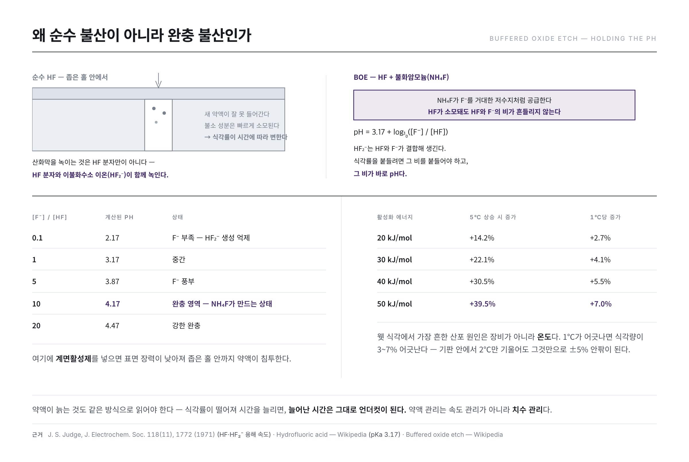
The standard chemical for dissolving oxide is hydrofluoric acid (HF). Inside a narrow hole, however, the limits of pure HF are stark.
- Fresh chemical struggles to get in — the narrower the hole, the slower the diffusion.
- The fluoride in HF is consumed quickly — the liquid inside the hole soon loses its etching power.
- The etch rate therefore changes with time — hard to control.
Enter BOE (Buffered Oxide Etch). It is HF mixed with ammonium fluoride (NH₄F), and Wikipedia's explanation is precise — "buffering HF with NH₄F gives a solution with a more stable pH, and therefore more stable concentrations of HF and HF₂⁻, and thus a more stable etch rate" (Buffered oxide etch). The reaction and quantitative data are published too — SiO₂ + 4HF + 2NH₄F → (NH₄)₂SiF₆ + 2H₂O, and a 6:1 mixture of 40% NH₄F and 49% HF etches thermal oxide at about 2nm per second at 25℃.
Why holding the pH stabilises the etch rate
Go one step into the causality of that sentence and the meaning of buffering becomes clear. It is not HF molecules alone that dissolve the oxide. A classic 1971 study expressed the dissolution rate of oxide in acidic fluoride solutions as a linear function of the concentrations of HF molecules and bifluoride ions (HF₂⁻), and showed that the coefficient on HF₂⁻ is far larger than that on HF — the real protagonist is HF₂⁻ (J. S. Judge, J. Electrochem. Soc. 118(11), 1772 (1971)).
But HF₂⁻ is formed from HF combining with F⁻. So holding the etch rate means holding the ratio of HF to F⁻, and that ratio is precisely the pH. The acid dissociation constant of HF is pKa 3.17 (Hydrofluoric acid), giving
pH = 3.17 + log₁₀([F⁻] / [HF])
| [F⁻] / [HF] | Computed pH | State |
|---|---|---|
| 0.1 | 2.17 | F⁻ starved — HF₂⁻ formation suppressed |
| 1 | 3.17 | midpoint |
| 5 | 3.87 | F⁻ rich |
| 10 | 4.17 | buffered region — what NH₄F creates |
| 20 | 4.47 | strongly buffered |
The pH values were computed directly from the formula. In pure HF, F⁻ comes only from HF's own dissociation, so the ratio is very small and even that small value drifts as etching consumes HF. Add NH₄F and F⁻ exists as a huge reservoir, so equilibrium immediately replenishes HF as it is consumed. A buffer does not protect the pH so much as protect the concentration of the etching species; pH is the gauge that reads the state.
How etch rate moves with NH₄F concentration has been measured directly (A. Proksche, G. Nagorsen, D. Ross, J. Electrochem. Soc. 139(2), 521 (1992)). That the etching of silicate films in HF-based solutions is a reaction-rate-limited process following Arrhenius behaviour with temperature has also been reported quantitatively (G. A. C. M. Spierings, J. Mater. Sci. 28, 6261 (1993)).
Add a surfactant and surface tension drops, letting the liquid penetrate a narrow hole. That surfactant-added buffered HF greatly improves wettability and thus allows uniform treatment even in fine structures was established as early as 1990 (H. Kikuyama, N. Miki, K. Saka et al., IEEE Trans. Semicond. Manuf. 3(3), 99 (1990)). The buffer keeps supplying fluoride while the surfactant opens the path.
Temperature is the etch rate
The most common source of variation in wet etching is not the equipment but temperature, because reaction rate is bound exponentially to it.
etch rate ∝ exp(−Ea / RT) — Ea: activation energy, R: gas constant, T: absolute temperature
Take an activation energy of a few tens of kJ/mol and raise the temperature just 5 degrees, from 25℃ to 30℃:
| Activation energy | Increase over 5℃ | Per 1℃ |
|---|---|---|
| 20 kJ/mol | +14.2% | +2.7% |
| 30 kJ/mol | +22.1% | +4.1% |
| 40 kJ/mol | +30.5% | +5.5% |
| 50 kJ/mol | +39.5% | +7.0% |
The table was computed by putting 298K → 303K into the Arrhenius expression. One degree off means three to seven percent off in the amount etched. Translated into the uniformity formula of post 14, a mere 2℃ tilt across a substrate produces a uniformity loss of around ±5% by itself. That is why wet etch equipment invests so heavily in bath temperature and spray pattern.
Chemical life should be read the same way. As etching proceeds, dissolved metal ions accumulate and the active component depletes. The etch rate falls, so the time is extended — and extending the time extends the undercut with it. An ageing bath is not only a speed problem but a line-width problem.
A special caution for silver wiring — migration
Silver-based materials used for pixel electrodes carry a hazard of their own. If silver ions dissolved during etching are reduced again and left as fine particles, they become a problem later.
Given the right conditions, silver undergoes migration. With a voltage difference between conductors and moisture along the path, silver grows in a branching dendrite shape and bridges the gap, shorting the lines (Electromigration). This growth is not random but has reproducible form, and studies have described the morphology and growth of the dendrites quantitatively (C. Dominkovics, G. Harsányi, Microelectron. Reliab. 48(10), 1628 (2008)).
In principle, once the conditions are satisfied it is only a matter of time, so there are two responses — minimise silver particles and design the spacing between lines as wide as possible.
Three layers at once — multi-step etching
Cutting a three-layer metal with a single chemistry easily collapses the profile because of galvanic effects. So the etch is sometimes split into several steps. If the upper and lower layers differ greatly in character, for instance, chemistries suited to each are applied in sequence.
Splitting has its own trap, though, because one chemistry may attack a lower layer that is already exposed. In the end it becomes a combinatorial design of composition × sequence × time, and that is the core of wet etch engineering.
Three common misconceptions
- "Wet etching cannot be precisely controlled." The direction cannot be controlled, but the ratio can. Undercut over thickness sets the sidewall angle, and that ratio is tuned by chemistry and PR adhesion. The taper a wet etch gives is actually an advantage for covering with the next dielectric.
- "An old bath is merely weaker." Weaker means longer times, and the extra time becomes undercut. Bath management is not speed management but dimension management.
- "Galvanic action is a defect to be avoided." If it cannot be avoided, better to make it a design variable. That balancing etch rates through metal combination and thickness ratio yields the slope you want is stated explicitly in the patent.
What the floor watches — three control points
- Bath life and composition — as etching proceeds, dissolved metal accumulates and the etch rate changes. Concentration and metal-ion levels are monitored, with periodic replenishment and replacement.
- Temperature and flow — chemical reaction rate is temperature sensitive. Nozzle spray pattern and substrate transport speed decide uniformity.
- Profile and residue — is the sidewall angle as designed, has an overhang or eave formed, is the bottom of the hole clean? Checked periodically by cross-section.
Once etching is done, the PR has served its purpose. The next post (post 17) is the strip process that removes the resist that has finished its job — it looks simple, but peeling off a PR that has hardened, without damaging anything, is trickier than it sounds.
References
- J. S. Judge, "A Study of the Dissolution of SiO2 in Acidic Fluoride Solutions," J. Electrochem. Soc. 118(11), 1772 (1971) : the original expression of oxide dissolution rate as a function of HF and HF₂⁻ concentrations — the basis of the buffering discussion
- A. Proksche, G. Nagorsen, D. Ross, "The Influence of NH4F on the Etch Rates of Undoped SiO2 in Buffered Oxide Etch," J. Electrochem. Soc. 139(2), 521 (1992) : measured oxide etch rate against buffer concentration
- H. Kikuyama, N. Miki, K. Saka et al., "Surface active buffered hydrogen fluoride having excellent wettability for ULSI processing," IEEE Trans. Semicond. Manuf. 3(3), 99 (1990) : buffered HF with surfactant for improved wettability
- G. A. C. M. Spierings, "Wet chemical etching of silicate glasses in hydrofluoric acid based solutions," J. Mater. Sci. 28, 6261 (1993) : composition and temperature dependence of silicate film etching in HF-based solutions
- Y. Wang et al., "Area Ratio of Cathode/Anode Effect on the Galvanic Corrosion of High Potential Difference Couple," IOP Conf. Ser. Mater. Sci. Eng. 322, 022046 (2018) : experiment showing cathode/anode area ratio governing galvanic corrosion rate
- C. Dominkovics, G. Harsányi, "Fractal description of dendrite growth during electrochemical migration," Microelectron. Reliab. 48(10), 1628 (2008) : quantitative description of dendrite morphology grown by electrochemical migration
- US 7,767,478 B2 — Thin film transistor array panel and method for manufacturing the same : bidirectional description of galvanic acceleration and deceleration, the Al (−1.66V) and Cu (+0.337V) electromotive forces, and sidewall slope control by balancing etch rates
- US 6,930,749 B2 — Method for forming metal line of liquid crystal display device : the overhang defect produced by galvanic corrosion in a Mo/Al bilayer
- Buffered oxide etch — Wikipedia : BOE composition (HF + NH₄F), the reaction, pH and etch-rate stabilisation, and the 25℃ rate of about 2nm/s for the 6:1 solution
- Hydrofluoric acid — Wikipedia · Standard electrode potential (data page) : the pKa of 3.17 for HF and the standard electrode potentials used in the difference table
- Galvanic corrosion — Wikipedia · Electromigration — Wikipedia : the general principle of galvanic corrosion and the migration phenomenon
- Etching (microfabrication) — Wikipedia : the definition of undercut (bias) in isotropic etching