Once etching is done, the photoresist (PR) has finished its job. Now it has to come off. At first glance this looks like the simplest process of all, but in practice it ranks among the most demanding — because the PR has hardened on its way through everything that came before. This installment is about the strip process.
Why It Doesn't Just Peel Off
Freshly coated PR dissolves easily in organic solvents. But its character changes as it goes through the process.
- Hard bake (installment 12) — we deliberately baked it at 130–150℃ to harden it. The goal was to make it survive etching, but that also makes it harder to remove.
- Dry etching (installment 15) — high-energy ions striking the surface rearrange the carbon bonds, forming a tough crust on the PR.
- Ion implantation (installment 8) — dopant ions punching through the PR harden the surface the same way. The higher the dose, the worse it gets.
In other words, what the strip has to deal with is not "the original PR" but "PR that has been transformed by several processes". That is why strip conditions depend on what the immediately preceding process was.
Chemically, all three cases end up going the same way. When the novolac resin that forms the PR backbone takes heat and ion bombardment, hydrogen leaves first, and the sites left behind bond to each other, linking ring to ring. The surface layer ends up less like a polymer and more like an amorphous carbonized network. To dissolve in a solvent, chains have to loosen and disperse; once the film has become a network, it is simply no longer in a dissolvable state. Ever since a 1989 study of the ashing of ion-implanted resist established that this hardened layer must be treated as a phase distinct from the bulk PR, strip design has been built on the premise that you attack the crust and the body separately.
What Happens Under the Crust — Popping
The real reason the hardened layer is troublesome lies elsewhere. The crust is not only hard, it is also gas-tight.
Put the substrate in an asher and raise the temperature, and the soft PR under the crust decomposes into gas first. But that gas has nowhere to go. Internal pressure builds until, at some point, the crust bursts. This is popping. Fragments of the burst crust scatter throughout the chamber, and some of them settle back on the substrate — the material you were trying to remove turns into a particle that is harder to remove.
US Patent 5,811,358, which addresses stripping after high-dose ion implantation, takes this problem head on. The target dose range is 1×10¹⁵ to 5×10¹⁶ ions per square centimeter — exactly where the crust grows thickest. The remedy was splitting the temperature. A first stage runs below 220℃ (150–220℃ preferred) for only 10–20 seconds to quietly work through the crust; only once the crust is open does a second stage go above 220℃ for 30–60 seconds to burn out the body. Reverse the order and go hot from the start, and the interior boils before the crust opens, which is precisely what makes it pop. It is a fine illustration that in stripping, temperature is a question of sequence rather than of intensity.
How It Comes Off — Swelling and Delamination
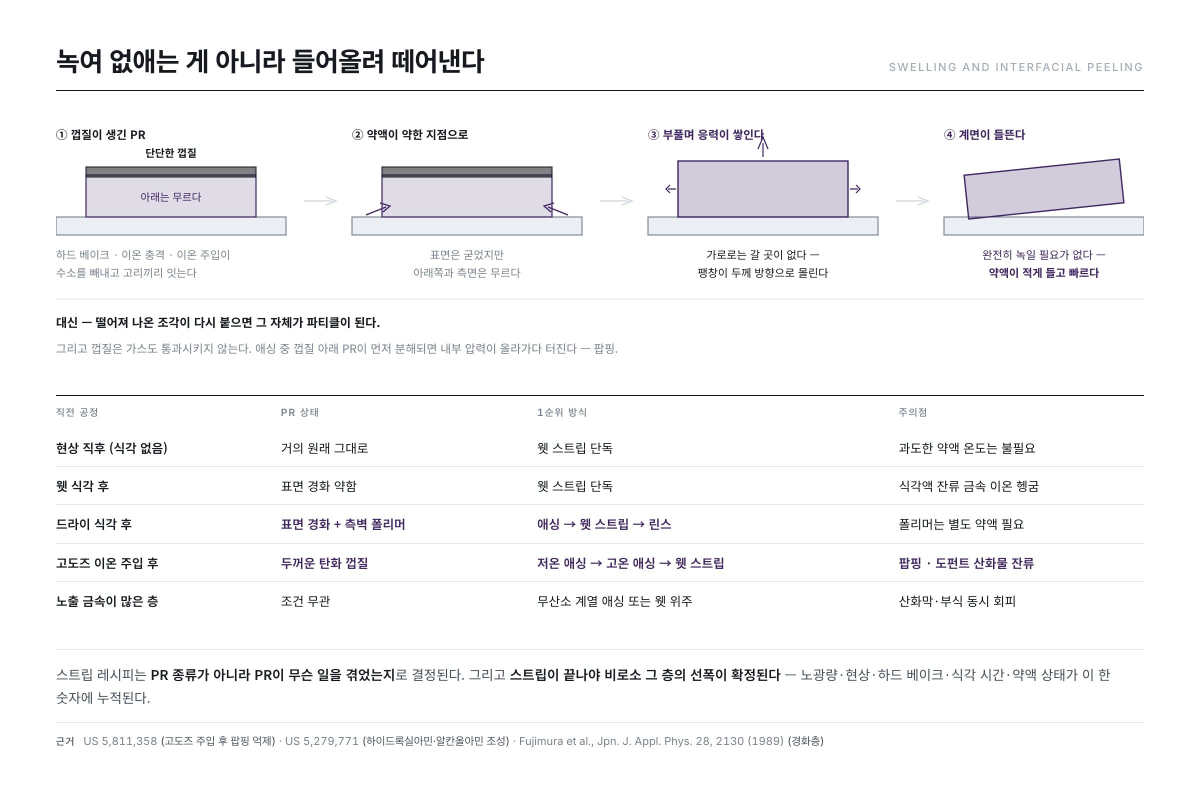
The principle of a wet strip is closer to lifting the film off than dissolving it away.
A PR film is not uniformly hard. The surface may be cured, but the underside and the sidewalls stay relatively soft. The strip chemistry works its way in through these weak points and soaks into the PR. The PR then swells, its adhesion to the film below breaks, and it finally lifts and comes away in chunks.
Why should swelling alone break the adhesion? The PR film is pinned to the underlying layer on every side, so it cannot expand laterally. When solvent enters and the volume grows, that expansion is forced into the thickness direction, while in the lateral direction a compressive stress builds up with nowhere to go. The moment that stress exceeds the bonding energy at the interface, the film starts to lift at the edges. Once lifted, chemistry floods into the gap and delamination accelerates. This is why a strip does not look like "gradually thinning away" but like "nothing happening for a while, then the whole thing coming off at once." A 2005 study that separated swelling, dissolution and removal in real time by tracking refractive index and thickness showed by measurement that these two phases are real: apparent thickness increases first, then falls abruptly.
The advantage of this mechanism is obvious — there is no need to dissolve the PR completely, so chemical consumption is low and processing is fast. The drawback is just as obvious — if a detached fragment of PR lands back on the substrate, it becomes a particle in its own right. That is why, for strip equipment, rinsing the detached fragments away immediately matters just as much as getting the film off.
Two Methods, and the Combination
Wet Strip — With Chemistry
This uses a dedicated stripper chemistry. Organic solvent and amine types are typical, and alkaline types are also used. It does little damage to metal wiring and can process a large area in a single pass.
You do, however, have to watch compatibility with the metals. As we saw in the previous installment (16), metals such as aluminum are vulnerable to alkalis, so you have to find a composition that strips the PR well while leaving the wiring beneath it alone. That is the central requirement in choosing a stripper.
Dry Ashing — With Oxygen Plasma
This is the ashing we saw in installment 15. Oxygen radicals burn the organic material away as carbon dioxide and water. It works well on heavily cured PR, and since no liquid is involved there is little risk of particles redepositing.
In exchange, plasma damage and static charge come along for the ride, and the oxygen can oxidize exposed metal surfaces. Once an oxide forms, contact resistance with the next layer goes up.
In Practice, You Use Both
So production lines usually combine them in sequence. First ashing burns off the hardened crust, then a wet strip removes the remaining bulk, and finally a thorough rinse. If the preceding process was ion implantation, the ashing share goes up; right after a wet etch, a wet strip alone may be enough.
The difference in character between the two methods sums up like this.
| Item | Wet strip (chemistry) | Dry ashing (oxygen plasma) |
|---|---|---|
| Removal mechanism | Penetration → swelling → interfacial delamination (physical lift-off) | Oxidative decomposition by oxygen radicals (chemical combustion) |
| Against a hardened crust | Unfavorable — solvent cannot unravel a network | Favorable — the carbon is simply burned away |
| Effect on exposed metal | Corrosion risk (alkalis and amines vs. aluminum, copper) | Oxidation risk (contact resistance rises) |
| Particles | High risk of detached fragments redepositing | Low — but popping makes it the worst case |
| Damage | Almost none (chemical damage only) | Plasma charging, charge damage, electrostatic breakdown |
| By-product handling | Spent chemistry and wastewater treatment | Exhaust treatment (carbon dioxide, water vapor, unbroken fragments) |
| Temperature range | Roughly 50–150℃ (depends on formulation) | Roughly 80–350℃ (depends on gas mix) |
The Preceding Process Sets the Recipe
A strip recipe is decided not by the type of PR but by what the PR has been through. Translated into practical rules of thumb, it looks roughly like this.
| Immediately preceding step | State of the PR | First-choice method | Watch out for |
|---|---|---|---|
| Right after development (no etch) | Nearly as coated | Wet strip alone | No need for aggressive chemistry temperature |
| After wet etch | Weak surface hardening | Wet strip alone | Rinse out metal ions left by the etchant |
| After dry etch | Surface crust plus sidewall polymer | Ashing → wet strip → rinse | The polymer needs its own chemistry |
| After high-dose implantation | Thick carbonized crust | Low-temperature ashing → high-temperature ashing → wet strip | Popping and dopant oxide residue |
| Layers with much exposed metal | Regardless of condition | Oxygen-free ashing, or mainly wet | Avoid oxide growth and corrosion at once |
What Ashing Actually Burns
We say ashing "burns the PR away," but working out what burning means numerically gives a real sense of the scale of this process. Take the novolac repeat unit as C₈H₈O on a cresol-formaldehyde basis (molar mass about 120.2) and assume complete oxidation, and the reaction is:
C₈H₈O + 9.5 O₂ → 8 CO₂ + 4 H₂O
Assume a PR density of 1.2 g/cm³, the usual figure for an organic polymer, and suppose 1 m² of substrate is covered with 2 µm of PR. That is 2 cm³ of volume, 2.4 g of mass, about 0.0200 mol of repeat units. Feeding that into the equation, the oxygen required is 0.190 mol — about 4.25 L at standard conditions. What comes out is 0.160 mol (about 3.58 L) of carbon dioxide and 1.44 g of water.
This is why an ashing chamber flows thousands of sccm of oxygen a minute, and why moisture condensation and organic residue are perennial problems in the exhaust line. Ashing is not an "erasing" process but a process that converts a solid into a gas and carries it out; if there is not enough flow to carry it, the decomposition products solidify again inside the chamber.
When You Take the Oxygen Out — Oxygen-Free Plasma
The weakness of oxygen ashing is oxidation of exposed metal. If a readily oxidized metal such as copper is exposed, or a low-k dielectric containing organic components sits nearby, oxygen radicals will not confine themselves to burning the PR. Hence a plasma that uses no oxygen at all. US Patent 6,281,135 proposes nitrogen with 3–5 percent hydrogen by volume, plus a fluorine-bearing gas such as CF₄ or CHF₃ at under 10 percent by volume. Conditions are 80–350℃ (80–180℃ preferred for organic low-k films), 0.5–10 Torr, 500–2,000 W. Instead of oxygen, hydrogen radicals lift the organic material away in a reducing atmosphere while a small amount of fluorine works on residue.
The measured figures given in that patent, on a carbon-doped oxide, were a PR removal rate of about 8,700 Å per minute against a low-k loss of about 449 Å per minute — a selectivity of roughly 19:1. At that rate, clearing 2 µm (20,000 Å) of PR takes about 2.3 minutes. That single number explains why ashing a single substrate is a matter of minutes, and why a line does not try to finish everything with ashing alone.
The Chemistry of the Stripper — Amines, Hydroxylamine, and Corrosion
Wet strip chemistries get lumped together as "solvents," but a real formulation is a team of components with different jobs. US Patent 5,279,771, arguably the archetype of this family, proposed a combination of hydroxylamine (NH₂OH), an alkanolamine, and a polar solvent. The claims call for at least 5 percent hydroxylamine by weight, at least 10 percent alkanolamine by weight, and 5–85 percent polar solvent, applied at 50–150℃ for 2 to 30 minutes.
The division of labor runs as follows. The alkanolamine, as a base, ionizes and solubilizes the novolac resin; the polar solvent carries away the loosened chains; and the hydroxylamine, a strong reducing agent, reduces and lifts off the oxidized and organometallic residue the plasma left behind. It is thanks to that third role that this patent could name even polyimide-type coatings cured at 400℃ among its targets.
The catch is that amines are strong bases, and as we saw in installment 16, aluminum dissolves in alkali. So the follow-on patent in the same family, US 5,672,577, adds a chelating agent — a substance such as 1,2-dihydroxybenzene (catechol) that captures metal ions and keeps the corrosion reaction from proceeding on the wiring surface. The aluminum corrosion data in that patent shows at a glance why chelate and solvent design matter. Below is the percentage thickness loss of a 6,000 Å aluminum film sputtered on silicon after immersion in chemistry at 65℃.
| Immersion time (65℃) | Composition B — 50% hydroxylamine + 50% alkanolamine | Composition C — 10% hydroxylamine + 45% alkanolamine + 45% polar solvent |
|---|---|---|
| 10 minutes | 1.5% | 0.8% |
| 15 minutes | 2.3% | 1.0% |
| 20 minutes | 3.1% | 1.2% |
Composition B loses 3.1% of its thickness in 20 minutes. On 6,000 Å that is about 186 Å — not a value you can ignore once you convert it into line resistance. Composition C, which dilutes the amine with nearly half polar solvent, loses 1.2% (about 72 Å) in the same time, less than half as much. But cut the amine and you also cut the stripping power. Designing a stripper comes down to choosing a coordinate between "power to strip" and "power to leave the wiring intact", and this table gives measured points on that plane.
Residue — The Failure You Can't See
The signature defect of the strip is residue. There are two kinds.
- PR residue — fragments of photoresist that did not come off. Once the next layer is deposited on top of them, they become a defect you can never fix.
- Sidewall polymer — a compound layer formed on the sidewalls during dry etching. Its character differs from PR, so ordinary strippers do not remove it well. That is why the BOE from installment 16 is also used to clear this residue.
Sidewall polymer is so stubborn because it is not PR at all. During a dry etch, carbon and hydrogen shed by the PR, fluorine and chlorine from the etch gas, and species knocked loose from the film and metal being cut all redeposit together on the sidewall. The result is a mixed layer of organometallic compounds and metal oxides, so ashing aimed at organics burns off only the carbon skeleton and actually leaves the metal component behind, hardened into an oxide. Chelating agents and reducing agents in the stripper, and a hydrofluoric-acid-based finish, exist to deal with that "leftover metal."
After high-dose implantation another residue joins in: the dopant itself, lodged inside the PR. Arsenic, phosphorus and boron turn into oxides after oxygen ashing and stay on the surface, and since they are not organic, no amount of extra ashing will make them go away. That is exactly why US 5,811,358 makes its final stage an oxygen-free nitrogen-hydrogen atmosphere.
Whether residue remains is checked by optical inspection and cross-section observation, but the fine stuff only reveals itself in the next process — contact resistance comes out high, or the deposited film lifts at that exact spot. This is where the saying "the strip is the process whose problems are found downstream" comes from.
The Line Width Is Finally Fixed
In installment 14 we talked about CD bias — the difference between the line width right after development (DI) and the line width after strip (FI). Which means the line width of that layer is not settled until the strip is done.
The measurement at this point is the report card for the entire process. Exposure dose, development conditions, hard bake temperature, etch time, chemical condition — every upstream variable accumulates into this one number. That is why FI CD is managed not as a mere inspection item but as a health indicator for the whole line.
There is diagnostic value in it too. If DI is normal and only FI has drifted, the cause lies with etching; if DI is already off, it lies with exposure or development. For the same CD deviation, looking at DI and FI together tells you who the culprit is.
Three Common Misconceptions
"Soak it long enough and it will all come off." — No. Extend the time and it is the amount of wiring being eaten away, not the amount of PR being removed, that hits its limit first. Look at the table above: composition B accumulates loss almost linearly, 1.5% at 10 minutes and 3.1% at 20. The answer to PR that will not come off is not more time but a different method.
"Ashing does no damage." — That means no liquid is used, not that it is harmless. Plasma brings charge with it, so charge damage that punches through a dielectric is possible; oxygen oxidizes exposed metal; and if popping occurs it produces far worse particles than a wet strip ever would.
"The strip is part of cleaning." — Their purposes differ. The strip removes, as planned, a film you deliberately put down; the cleaning we take up from the next installment deals with things you never put there. The two do travel together, though, because washing away the fragments and residual chemistry the strip creates is cleaning's first assignment.
And Then It Repeats
Now is the time to bring back something installment 1 hinted at. This cycle of deposition → photo → etch → strip → clean does not end after one lap. It repeats from the beginning for every wiring layer.
Build the gate wiring, cover it with an insulating film, then photo, etch, strip again. Build the source and drain, then another insulating film, then photo, etch, strip again. Open the contact holes, form the pixel electrodes… a single backplane goes around this loop many times. And every lap comes with a cleaning step — because the surface has to be cleared before the next layer goes on.
From the next installment (18) on, cleaning is the subject. Why particles you cannot even see determine yield, and what force exactly is holding those particles to the surface — we head into the story of surface physics.
References
- US 5,279,771 — Stripping compositions comprising hydroxylamine and alkanolamine (1994) : the hydroxylamine / alkanolamine / polar solvent formulation and its 50–150℃, 2–30 minute conditions
- US 5,672,577 — Cleaning compositions for removing etching residue with hydroxylamine, alkanolamine, and chelating agent (1997) : the chelating agent addition and the measured aluminum corrosion data used in the table above
- US 5,811,358 — Low temperature dry process for stripping photoresist after high dose ion implantation (1998) : two-stage split-temperature ashing to suppress popping, and handling of dopant oxides
- US 6,281,135 — Oxygen free plasma stripping process (2001) : the nitrogen-hydrogen plus trace fluorine chemistry, with measured 8,700 Å/min removal rate and selectivity
- Fujimura et al., "Ashing of Ion-Implanted Resist Layer", Jpn. J. Appl. Phys. 28, 2130 (1989) : an early study treating the implantation-hardened layer as distinct from the bulk
- Kawaguchi et al., "Low temperature, ion-enhanced, implanted photoresist removal", J. Vac. Sci. Technol. B 24, 651 (2006) : opening the hardened crust with ion assistance at low temperature
- Spuller et al., "Evaluating Photoresist Dissolution, Swelling, and Removal with an In Situ Film Refractive Index and Thickness Monitor", J. Electrochem. Soc. 152, G40 (2005) : separating the swelling phase from the dissolution phase in real time
- Plasma ashing — Wikipedia : the principle of oxygen plasma ashing and its reaction products
- Photoresist — Wikipedia : the composition of photoresist and the concept of removal (strip)
- Buffered oxide etch — Wikipedia : buffered hydrofluoric acid used for residue removal
- Critical dimension — Wikipedia : final line width control