In the previous article we looked at the forces that hold particles to a surface. This article is about beating those forces with chemistry. Every cleaning chemical aims at a different target — one dissolves oxide, one burns organics away, one pushes particles off. The order in which you use them is what a cleaning recipe really is.
Three chemicals, three targets
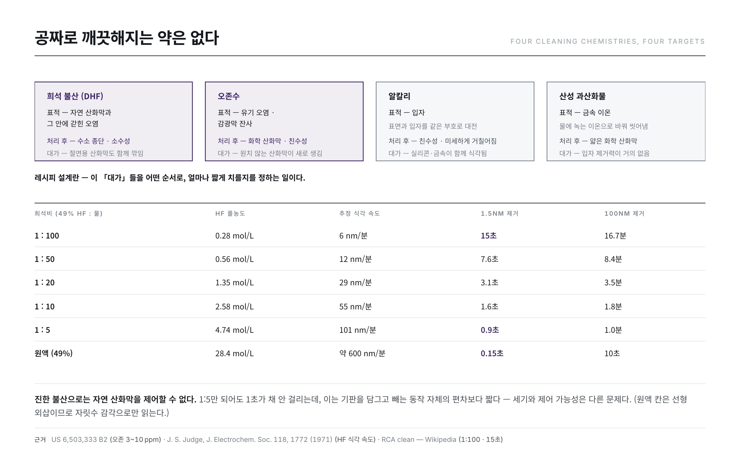
Let us lay out the map first. Choosing a cleaning chemical means choosing, at the same time, what you want removed and what you are willing to lose in exchange.
| Chemical | Primary target | Mechanism | Surface afterwards | Price paid |
|---|---|---|---|---|
| Dilute HF (DHF) | Native oxide and the contamination trapped inside it | Fluoride breaks Si–O bonds and dissolves the film | Hydrogen-terminated, hydrophobic | Exposed insulating oxide is etched too |
| Ozonated water | Organic contamination, resist residue | Oxidation breaks the carbon skeleton into carbon dioxide and water | Chemical oxide, hydrophilic | An unwanted oxide film grows |
| Alkali (ammonia, TMAH) | Particles | Charges surface and particle with the same sign so they repel | Hydrophilic, slightly roughened | Silicon and metals are etched as well |
| Acidic peroxide (HCl based) | Metal ions | Converts metals into water-soluble ionic forms and rinses them away | Thin chemical oxide | Almost no particle removal |
The last column is the point. No chemical cleans for free. Designing a recipe means deciding in what order, and for how short a time, to pay these prices.
1. Hydrofluoric acid — stripping the oxide
A silicon surface makes a thin oxide the moment it meets air. This native oxide is only nanometres thick and invisible, but it traps metal contamination underneath and blocks contact with the next layer.
Hydrofluoric acid is effectively the only chemical that dissolves it. The RCA cleaning sequence itself describes an intermediate step in which hydrofluoric acid diluted 1:100 or 1:50 is applied at room temperature for about 15 seconds to remove the thin oxide (RCA clean).
What is interesting is the nature of the surface afterwards. Once HF strips the oxide, the exposed silicon becomes hydrogen-terminated and therefore hydrophobic. A study reports this plainly — "a 20 s DHF dip turns the Si(100) surface hydrophobic" (Spectroscopic-ellipsometric study of native oxide removal by liquid phase HF process). The termination itself was confirmed directly by infrared spectroscopy in 1988: after HF treatment the surface shows a clear Si–H stretching absorption (Burrows, Chabal, Higashi et al., Appl. Phys. Lett. 53, 998, 1988). That surface is highly reactive, however, and re-oxidises as soon as it sees air — so even the waiting time before the next step becomes something you manage.
2. Ozone — burning the organics
Ozone is a powerful oxidiser. When it meets organic contamination it breaks it down into carbon dioxide and water. It is normally used as ozonated water — ozone dissolved in ultrapure water.
A patent captures both faces of ozone cleaning precisely: an ozone-containing solution greatly improves the removal of organic contamination from silicon, while the oxidising action grows an oxide film on the surface whose thickness increases with immersion time and ozone concentration. The same patent gives practical concentrations of about 1 to 20 ppm, preferably 3 to 10 ppm, and the resulting oxide as 5 to 20 Å (US 6,503,333 B2). Ozone, in other words, cleans and coats at the same time.
That property turns out to be useful. The bare, reactive surface left by HF can be stabilised by covering it with a clean, thin chemical oxide.
3. Alkali — pushing the particles away
The DLVO story from the previous article becomes practice here. Make the cleaning solution alkaline and both the substrate surface and the particle carry negative charge, so they repel each other. Nothing is dissolved; the particle is lifted electrically and carried off by the flow.
Different alkalis behave differently. Ammonium hydroxide is a weak base and relatively gentle, but volatile, so its concentration drifts. Potassium and sodium hydroxide are powerful but carry a serious risk of corroding metal lines, aluminium in particular. TMAH contains no metal ions, so contamination risk is low and the composition is stable, which makes it attractive for precision work — but it is toxic and demands care in handling (Tetramethylammonium hydroxide). Which alkali to use is therefore decided by what metals are exposed on the substrate.
How fast does HF actually strip?
"Removes the native oxide in 15 seconds" means nothing on its own. Let us put numbers to it.
The rate at which HF dissolves oxide is very nearly proportional to the concentration of the fluoride species in solution. A 1971 study first organised this relationship systematically: in acidic fluoride solutions the dissolution rate of the oxide depends to first order on the concentrations of HF and HF₂⁻, and is expressed as the sum of the two terms (Judge, J. Electrochem. Soc. 118, 1772, 1971). So knowing the dilution ratio is enough to compute the ratio of rates.
The assumptions are these. The stock is 49% HF with a density of 1.16 g/mL, diluted by volume. The absolute scale is anchored on the statement quoted above — 1:100, room temperature, 15 seconds. Taking the native oxide as 1.5 nm thick, that condition corresponds to 6 nm/min; dividing by the concentration gives a coefficient that is then applied to the other dilutions.
| Dilution (49% HF : water) | HF by mass | HF molarity | Estimated etch rate | To remove 1.5 nm | To remove 100 nm |
|---|---|---|---|---|---|
| 1 : 100 | 0.56% | 0.28 mol/L | 6 nm/min | 15 s | 16.7 min |
| 1 : 50 | 1.11% | 0.56 mol/L | 12 nm/min | 7.6 s | 8.4 min |
| 1 : 20 | 2.69% | 1.35 mol/L | 29 nm/min | 3.1 s | 3.5 min |
| 1 : 10 | 5.09% | 2.58 mol/L | 55 nm/min | 1.6 s | 1.8 min |
| 1 : 5 | 9.23% | 4.74 mol/L | 101 nm/min | 0.9 s | 1.0 min |
| Stock (49%) | 49% | 28.4 mol/L | about 600 nm/min | 0.15 s | 10 s |
The message is unmistakable. Concentrated HF cannot control a native oxide. Even at 1:5 the job takes less than a second, which is shorter than the run-to-run variation in simply dipping the substrate and pulling it out. To strip 1.5 nm reproducibly you have to deliberately make it slow. In cleaning, dilution is not about saving chemicals — it is about lifting the process time into a range you can observe.
One caveat: the table is a linear extrapolation. At higher concentrations, species such as the HF dimer become significant and the real rate runs faster than the calculation, so the stock row should be read as an order of magnitude only. In the dilute regime (1:100 to 1:10) the linear approximation holds well.
The arithmetic of ozonated water — is ppm enough?
Ozonated water is always specified in parts per million. Converting the patent's 3 to 10 ppm into molarity gives 60 to 210 µmol/L — more than ten thousand times more dilute than the hydrogen peroxide in the RCA solution we are about to meet (1.4 mol/L). Yet ozone still wins on organic removal, because the oxidising power itself is different.
The reason the concentration stays at ppm is that ozone barely dissolves in water. A study that measured the Henry's law constant of the ozone–water system across temperature concluded that solubility is very low and falls further as temperature rises (Sotelo, Beltrán, Benitez et al., Water Research 23, 1239, 1989). That is why ozonated water cannot be used hot, and why it must be used as soon as it is made.
Can a ppm-level concentration actually handle real contamination? Suppose 1 m² of substrate is covered by a 1 nm hydrocarbon film with a density of 0.9 g/cm³. Its mass is 0.90 mg, or 64 µmol of CH₂ units. If fully oxidising one CH₂ takes three oxygen atoms and one ozone molecule delivers one active oxygen, the ozone required is 193 µmol, or 9.3 mg.
Volume of ozonated water required = 9.3 mg ÷ concentration in mg/L
At 5 ppm that is 1.9 L/m²; at 3 ppm, 3.1 L/m²; at 10 ppm, 0.9 L/m². Given that one large substrate is several square metres, the requirement is tens of litres — and ozone standing in a static bath is consumed in seconds and decomposes on its own besides. That is why ozonated water is flowed continuously rather than used as an immersion bath. One patent indeed reports that supplying ozonated water as a spray mist raises the resist strip rate to roughly ten times that of an immersion method (US 6,399,513 B1). This is a process where delivery rate, not concentration, sets performance.
The classic of cleaning chemistry — RCA
The procedure that established the standard for semiconductor cleaning is the RCA clean, developed by Werner Kern in 1965 and published in 1970. Half a century later it is still used as the standard clean before high-temperature steps such as oxidation, diffusion, and CVD (RCA clean). As its developer set out in a retrospective 25 years later, the design idea was to build the sequence around hydrogen peroxide, with an alkaline step and an acidic step side by side (Kern, J. Electrochem. Soc. 137, 1887, 1990).
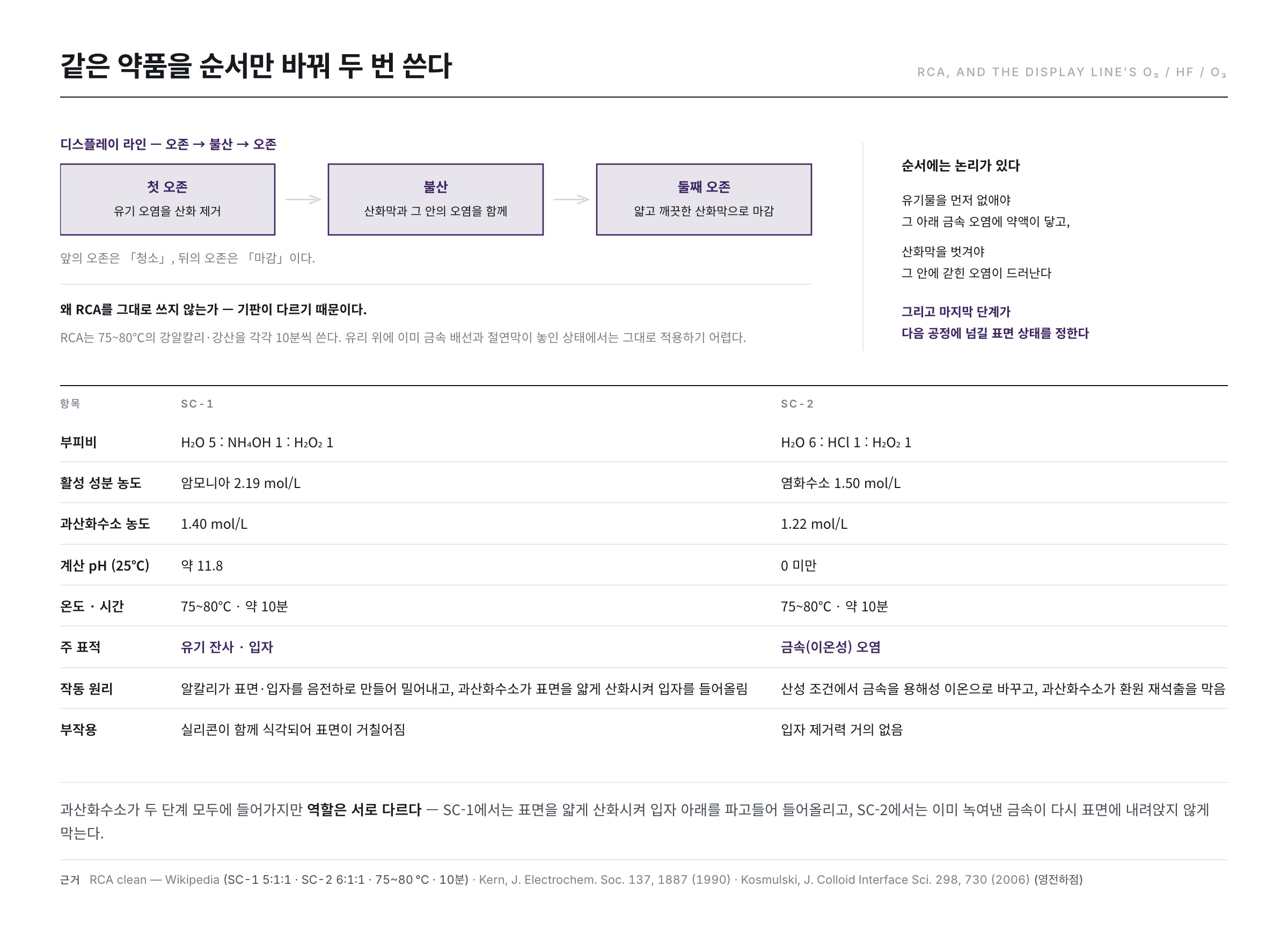
Converting the standard compositions (SC-1 = 5 water : 1 of 29% ammonium hydroxide : 1 of 30% hydrogen peroxide; SC-2 = 6 water : 1 of 37% hydrochloric acid : 1 of 30% hydrogen peroxide) into molarity using densities and molecular weights makes the intent visible.
| Item | SC-1 | SC-2 |
|---|---|---|
| Volume ratio | H₂O 5 : NH₄OH 1 : H₂O₂ 1 | H₂O 6 : HCl 1 : H₂O₂ 1 |
| Active species | Ammonia 2.19 mol/L | Hydrogen chloride 1.50 mol/L |
| Hydrogen peroxide | 1.40 mol/L | 1.22 mol/L |
| Calculated pH (25℃) | about 11.8 | below 0 |
| Temperature and time | 75–80℃, about 10 min | 75–80℃, about 10 min |
| Primary target | Organic residue and particles | Metallic (ionic) contamination |
| Mechanism | Alkali charges surface and particle negative so they repel; peroxide thinly oxidises the surface and lifts particles from beneath | Acid converts metals into soluble ions; peroxide prevents them from re-depositing |
| Side effect | Silicon is etched with the particles and the surface roughens | Almost no particle removal |
What stands out is that hydrogen peroxide appears in both steps, in different roles. In SC-1 it continuously oxidises a thin layer of the surface, undercutting particles and lifting them; in SC-2 it holds the dissolved metals in an oxidised state so they do not plate back out. One chemical serving as striker in the alkaline step and as defender in the acidic one.
A dilute HF step is often inserted between the two to strip the oxide. The order has its logic — organics have to go first for the chemistry to reach the metal contamination beneath them, and the oxide has to come off for whatever it has trapped to be exposed.
pH and zeta potential — the particles that refuse to leave
The claim that alkaline cleaning pushes particles away hides a condition: both the substrate and the particle must be negatively charged. Whether they are depends on what the particle is made of, because the point of zero charge introduced in the previous article differs from material to material. A comprehensive compilation of points of zero charge for metal oxides reports the following representative ranges (Kosmulski, J. Colloid Interface Sci. 298, 730, 2006).
| Material | Point of zero charge (pH) | Charge in SC-1 (pH ≈ 11.8) | Difficulty of removal |
|---|---|---|---|
| Silica (SiO₂) | about 2–3 | Strongly negative | Low — strong repulsion from the substrate |
| Titania (TiO₂) | about 5.5–6.5 | Negative | Low |
| Zirconia (ZrO₂) | about 6–7 | Negative | Moderate |
| Alumina (Al₂O₃) | about 8–9 | Weakly negative | High — repulsion is weak |
| Iron oxide (Fe₂O₃) | about 8–9 | Weakly negative | High |
Read it this way. The substrate surface — silicon oxide — has a point of zero charge of 2 to 3, so at pH 11.8 it sits nine units away and its charge is fully developed. A silica particle is the same, so the two repel strongly. An alumina or iron oxide particle, however, has a point of zero charge of 8 to 9 and is only three units away; its charge is barely developed, and the same SC-1 for the same time simply will not lift it.
This is what a "particle the clean does not touch" really is. The cleaning power is not lacking; the particle's material is close to neutral at that pH. That is why identifying the composition of a defect particle matters so much — if aluminium-bearing residue is the problem, the answer is not more chemistry but physical force.
The display line's sequence — O₃ / HF / O₃
Display processing reorganised these principles in its own way. The representative combination is a three-step ozone → HF → ozone treatment.
- First ozone — oxidises and removes organic contamination from the surface.
- HF — with the organics gone, strips the oxide and takes the contamination trapped inside it along with it.
- Second ozone — puts a thin, clean chemical oxide back onto the bare surface and hands it to the next step in a stable state.
It is a design that uses the same chemical twice, in different positions. The first ozone is the cleaning; the second is the finish.
Why not simply use RCA? Because the substrate is different. RCA uses strong alkali and strong acid at 75–80℃ for ten minutes each; with metal lines and insulating films already formed on a glass substrate, the wiring would not survive, and holding a large substrate uniformly at that temperature is itself a burden. Ozonated water and dilute HF, by contrast, are near room temperature, short, and gentle on metals. It is a redesign that reaches the same goal through milder conditions spread over more steps.
DHF and BOE — same fluorine, different character
The BOE we met in article 16 reappears in cleaning. The difference in character between dilute HF and BOE comes down to this.
- DHF — strips native oxide quickly, but its etch rate drifts with time and it attacks resist relatively strongly, because as the reaction proceeds the fluoride is consumed and the pH and species distribution move with it.
- BOE — the buffering agent keeps supplying fluoride, so the etch rate stays constant and it is relatively benign toward resist. It is the better choice for thick oxides or for the inside of narrow holes (Buffered oxide etch).
"Strip a native oxide briefly, or cut a thick film at a constant rate?" — the purpose decides. In the table above, removing 100 nm with 1:100 DHF would take 17 minutes, and there is no chance the solution composition stays put over that span. The longer the job, the more you need a buffered solution.
The limits of chemical cleaning
Chemistry does not solve everything. Three limits stand out.
First, embedded particles. As the previous article showed, the contact region deforms over time and begins to form chemical bonds; once it does, no amount of zeta potential tuning gets solution to the contact area at all.
Second, substrate damage. Raising the alkali concentration or extending the time to increase cleaning strength also etches the silicon surface itself. This is measured fact, not a qualitative worry — a study of how wafer surface roughness changes with wet processing showed that SC-1 roughens the surface, and does so more as the ammonium hydroxide fraction rises (Miyashita, Tusga, Makihara et al., J. Electrochem. Soc. 139, 2133, 1992). After that result, compositions with the ammonia fraction cut far below the standard value came into wide use. It is a textbook trade of particle removal against surface smoothness.
Third, the wall of selectivity. HF cannot tell a native oxide from an insulating one, and alkali cannot tell a particle from silicon. That is exactly the "price paid" column of the first table. With the path of turning up the strength blocked, the remaining direction is removing more at the same strength — introducing physical force.
Common misconceptions
"HF is strong, so just use it briefly." — Strength and controllability are different things. As the table showed, 1:5 HF takes off 1.5 nm in under a second, which is shorter than the variation in dipping and withdrawing the substrate: it cannot be reproduced. In cleaning, a good chemical is not a strong one but one that runs at an observable rate within the process time.
"Raise the ozone concentration and it cleans proportionally better." — Ozone's solubility in water is low and falls further with temperature, so concentration has a ceiling. Performance is set less by concentration than by the total ozone delivered per unit time, which is why the delivery method — spray, recirculation — makes the larger difference.
"One clean at the end is enough." — A surface straight out of HF is hydrophobic; one straight out of ozonated water is hydrophilic. Cleaning is also the act of resetting a surface to a specified state, and which state it should be handed over in is decided by the step that follows.
Next article
So physical force becomes necessary. The next article (20) covers physical cleaning — brushes, megasonics, high-pressure jets — and the ultrapure water and cleanroom that everything else presumes. It is also the last article in this series.
References
- Kern, "The Evolution of Silicon Wafer Cleaning Technology", J. Electrochem. Soc. 137, 1887 (1990) : the lineage and design philosophy of the RCA clean, written by its developer
- Judge, "A Study of the Dissolution of SiO₂ in Acidic Fluoride Solutions", J. Electrochem. Soc. 118, 1772 (1971) : etch rate first-order in HF and HF₂⁻ concentration
- Burrows, Chabal, Higashi et al., "Infrared spectroscopy of Si(111) surfaces after HF treatment", Appl. Phys. Lett. 53, 998 (1988) : spectroscopic evidence of hydrogen termination after HF
- Miyashita, Tusga, Makihara et al., "Dependence of Surface Microroughness of CZ, FZ, and EPI Wafers on Wet Chemical Processing", J. Electrochem. Soc. 139, 2133 (1992) : SC-1 roughening and its dependence on the ammonia fraction
- Kosmulski, "pH-dependent surface charging and points of zero charge", J. Colloid Interface Sci. 298, 730 (2006) : compilation of points of zero charge for metal oxides
- Sotelo, Beltrán, Benitez et al., "Henry's law constant for the ozone-water system", Water Research 23, 1239 (1989) : the low solubility of ozone in water and its temperature dependence
- Spectroscopic-ellipsometric study of native oxide removal by liquid phase HF process — International Nano Letters : a 20 s DHF dip turns Si(100) hydrophobic
- US 6,503,333 B2 — Method for cleaning semiconductor wafers with ozone-containing solvent : ozone at 1–20 ppm (preferably 3–10 ppm), grown oxide of 5–20 Å
- US 6,399,513 B1 — Ozonated DI water process for organic residue and metal removal processes : spray delivery raises the resist strip rate about tenfold over immersion
- RCA clean — Wikipedia : SC-1 (5:1:1) and SC-2 (6:1:1) compositions, 75–80℃ for 10 min, intermediate HF (1:100–1:50, 15 s)
- Buffered oxide etch — Wikipedia : composition of buffered HF and the stability of its etch rate
- Tetramethylammonium hydroxide — Wikipedia : properties of TMAH and handling precautions